J55 digital outputs, J55 digital outputs 237, Cable specification – MTS Model FlexTest SE User Manual
Page 237: Run/stop setup
J55 Digital Outputs
Models FlexTest® IIm/GT/SE Controller Hardware
FlexTest SE Controller Connections
237
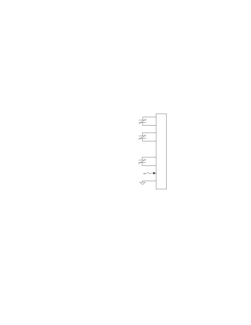
J55 Digital Outputs
Connector J55 Dig Out provides three general purpose digital outputs that can
send digital logic signals to external switches or logic devices.
•
The digital output relays are rated for a maximum of 1 Amp max, 30 V DC/
AC max.
•
The outputs are optically isolated.
Cable specification
The cabling information shown assumes a single cable destination (with an
overall shield). In other applications, the cable may have more than one
destination. For these applications an overall shield is not practical and non-EMI
connectors and back shells are permissible.
•
9 pin contact type D male EMI connector
•
Back shell–EMI metallized plastic
•
Cable–shielded twisted pairs as required (24 AWG minimum) with drain
wire(s) connected to the metallized backshell at the chassis.
Run/Stop setup
If required, digital output 1 (pins 1 and 2) can be set up as a Run/Stop connector.
Use the following procedures to set up this Run/Stop connector:
Relay Contact
Relay Contact
Relay Contact
To
External Device
J55
1
2
3
4
5
6
7
8
9
Channel 1 Output
Channel 2 Output
From
FT SE Controller
Channel 3 Output
+24 V