I/o carrier module, I/o carrier module 103 – MTS Model FlexTest SE User Manual
Page 103
Shunt Calibration/Bridge Completion Resistor
Models FlexTest® IIm/GT/SE Controller Hardware
FlexTest GT Controller Connections
103
Shunt Calibration/Bridge Completion Resistor Installation
On a typical system, shunt calibration and bridge completion resistor installation
is completed on the I/O Carrier module.
If you have purchased optional sensor cables with transducer ID modules, shunt
calibration and bridge resistors are installed on these modules.
I/O Carrier Module
Shunt calibration
connector
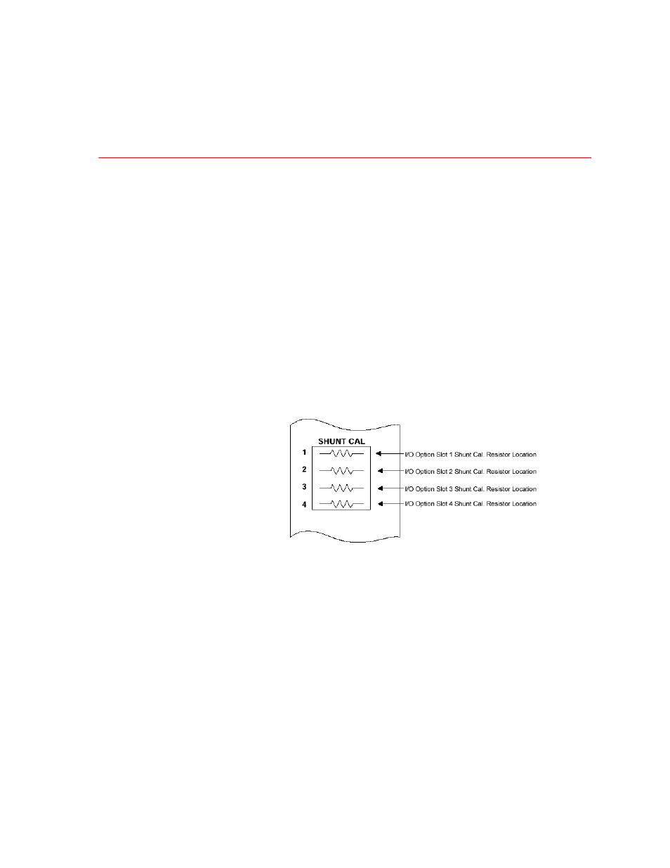
The I/O Carrier module has a shunt calibration connector on its front panel that
allows up to four shunt resistors (1 per slot) to be plugged in. The SHUNT CAL
connector is labeled to indicate which slot the shunt calibration resistor is tied to.
Each shunt calibration resistor is soldered to a 2-pin holder (MTS PN 011-433-
826). This holder plugs into the front panel connector shown below. Refer to the
493.40/41 Carrier I/O Shunt Calibration Kit (MTS PN 100-028-185) for more
detailed information on kit components and installation.
Bridge completion
circuits
Each of the four I/O option card slots on the I/O Carrier module provides support
for up to three bridge completion resistors as well as a shunt calibration resistor.
The bridge completion resistors can be installed into sockets on the I/O Carrier
printed wiring board. The shunt calibration resistor sockets are accessible from
the I/O Carrier front panel.