Motor type, How to select your system cable – Lenze EY System cables and system connectors User Manual
Page 60
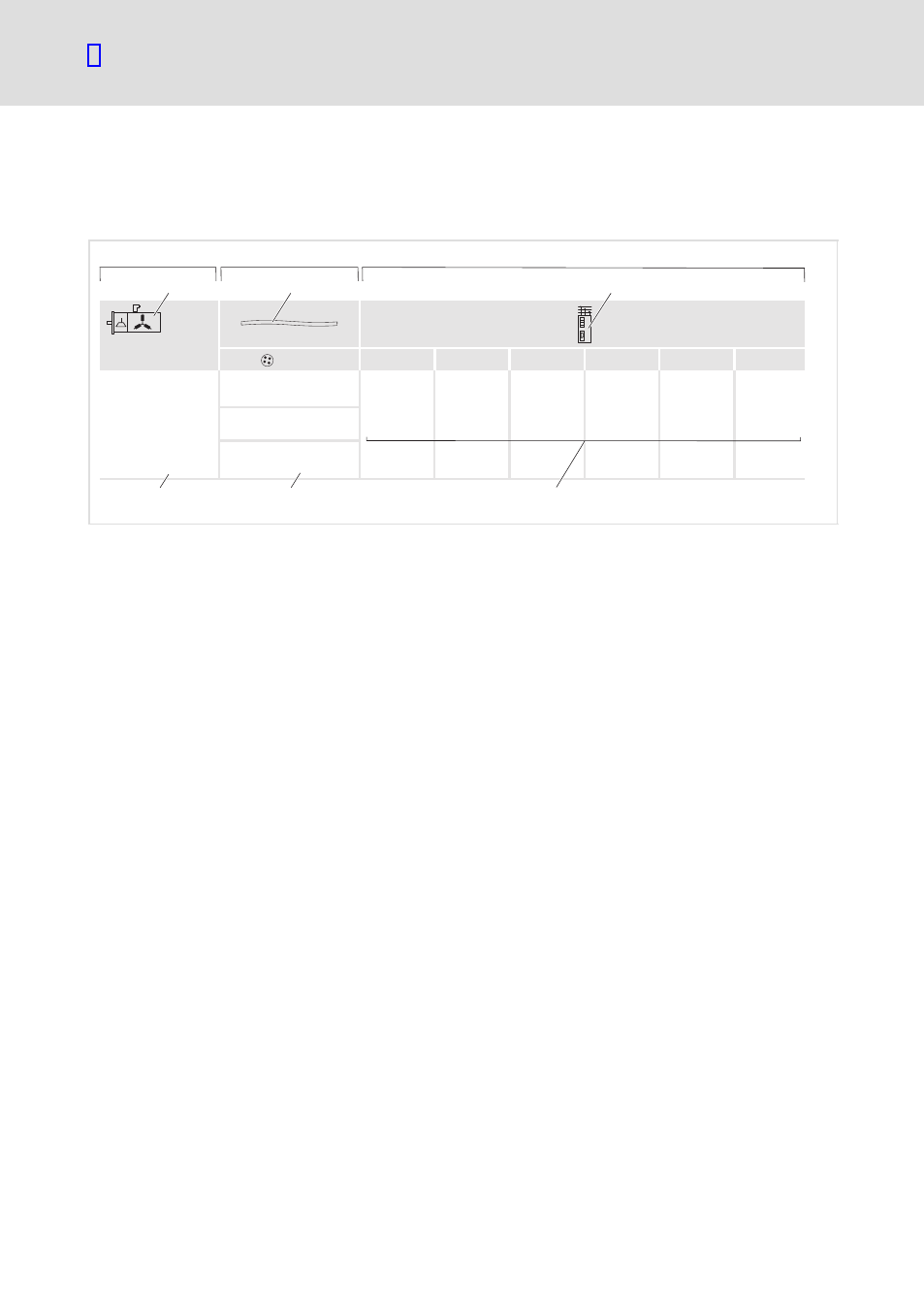
How to select your system cable
Motor cables
Motor type
l
60
EDSYPFLD EN 8.0
4.1.2
Motor type
The table gives more detailed information about the motor, the structure and
cross−section of the motor cable, and the connectionon the controller.
MCS06C41-...S00
MCS06C60-...S00
MCS06F41-...S00
MCS06F60-...S00
MCS06I41-...S00
MCS06I60-...S00
(4 x 1.0 + (2 x 0.5))
(4 x 1.5 + (2 x 0.5))
U, V, W, PE
X105, X107
X24, X25
(4 x 2.5 + (2 x 0.5))
[mm ]
2
9300
9400
ECS
U
V
W
1
0
2
3
4
5
hb_tab_01
0 Self−ventilated motor with plug
1 Motor cable
2 Controller
3 Motor types
4 Structure and cross−section of the motor cable
5 Controller terminals
ƒ
Column
describes which motor type is to be connected to the controller.
– The symbol may represent a motor with a plug or a terminal box.
ƒ
Column
gives more detailed information about the motor cable:
– Here, the symbol stands for the extension/connection cables. The exact product
key of these motor cables can be seen from the following two tables.
– The motor cables in this example are shielded four−core cables with the
parentheses representing the shield. Within this shield, another two−core cable is
laid.
– Alternatively, all of the three motor cables can be connected to all of the
synchronous servo motors specified.
– The assignment of the cable cross−section to the motor type is valid for the
conditions of the permissible current loading in accordance with EN 60204−1, IEC
60354−2−52 for trailing cables, table A.52−5, laying system C, continuous operation
with motor standstill current I
0
, and an air temperature of 45°C.
– If the conditions vary (regional standards, regulations, laying systems, bundling,
ambient conditions, cable types, motor utilisation), the responsibility for installing
a corresponding motor cable lies with the user.
ƒ
Column
contains the controller types.
– The motor cable is applied to the specified terminals of the different controllers.