2 crystalsix – INFICON XTC/C Thin Film Deposition Controller User Manual
Page 74
3 - 10
IP
N 07
4-
18
3X
XTC/C - XTC/2 Operating Manual
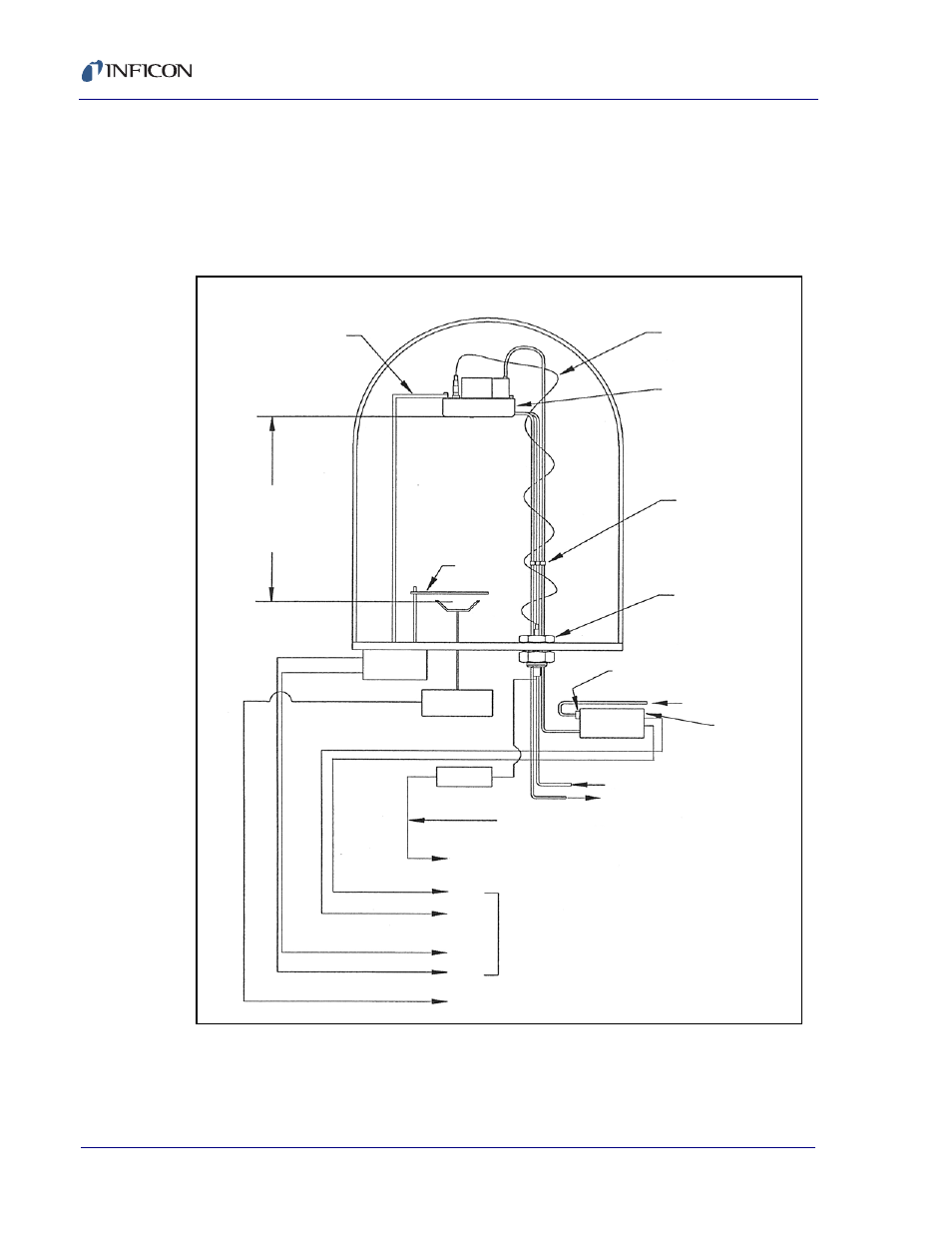
3.5.2 CrystalSix
Installing the CrystalSix transducer requires that the CrystalSwitch
configuration switches be set appropriately; refer to
Follow the guidelines in the CrystalSix Manual (IPN 074-155) and
. If
the unit is configured for one CrystalSix, it must be connected to Sensor 1.
Figure 3-5 CrystalSix Installation for XTC/2 and XTC/C
Typical System Setup
Solenoid
Assembly
Source
Controller
Pneumatic
Actuator
Source Shutter 1
Sensor Shutter 1
(5)
(6)
(1)
(2)
Source 1 or 2
Sensor 1 or 2
IPN 757-305-G15, G30 or G100
Water In
Water Out
Orfice
IPN 059-172
Air 90-110 PSI Max.
IPN 007-199
XTC/2 or XTC/C
System I/O
Connector
(Typical)
(Pin #)
XIU
Source
Source
Shutter
Min. Flow
200 cc/min
@ 30 °C max.
In
Out
1" Bolt
750-030-G1
or
2.34" ConFlat
002-080
Braze Connections
or Adapters
CrystalSix
IPN 750-260
Coaxial Cable
30’ Length Std.
IPN 007-044
Support Bracket
(Not Provided)
10" Min.
Source to
Sensor
Distance