INFICON XTC/C Thin Film Deposition Controller User Manual
Page 39
2 - 11
IP
N 07
4-
18
3X
XTC/C - XTC/2 Operating Manual
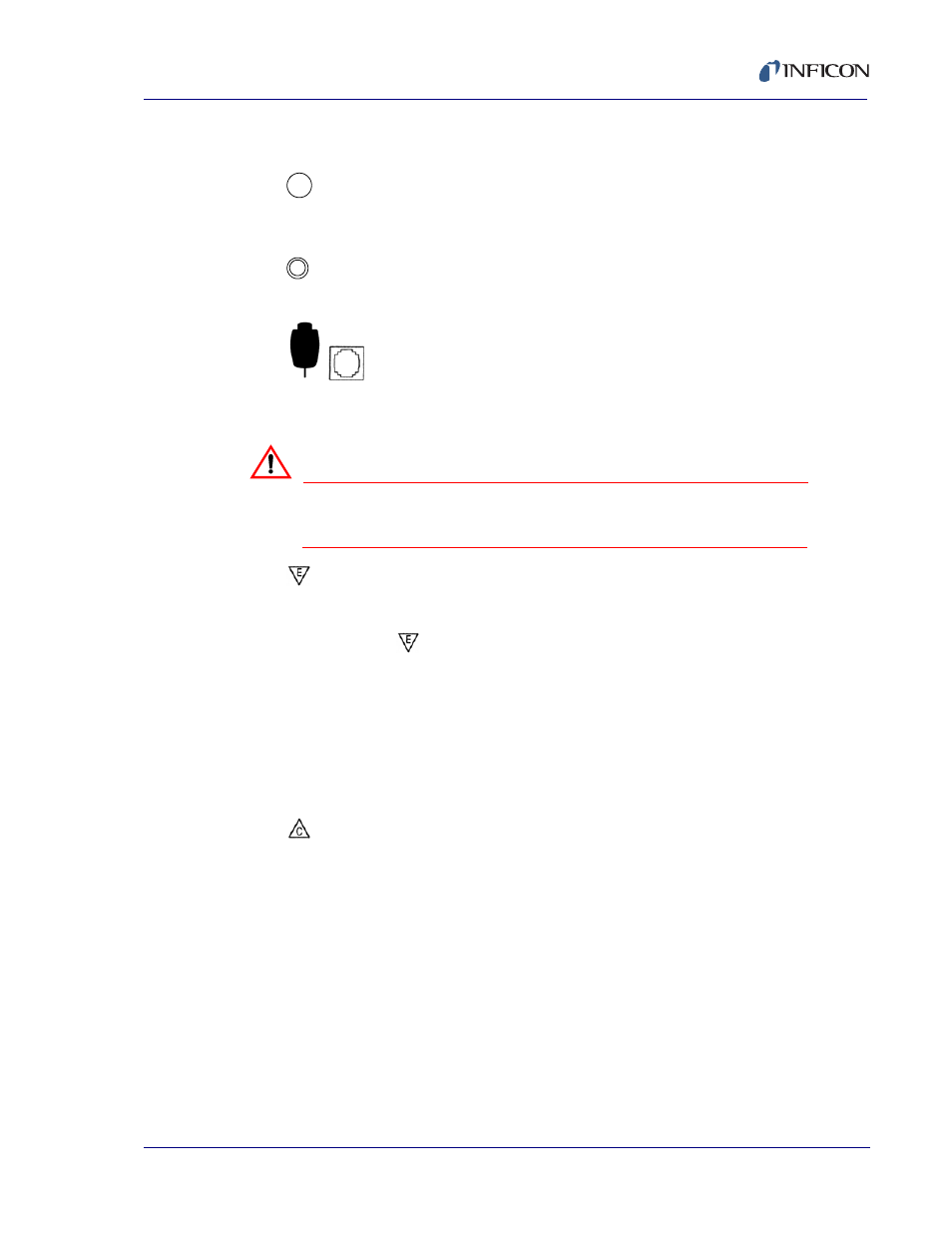
9— ON/STBY
Switches secondary power of the instrument between ON and STANDBY.
10—
Green LED indicates that the unit is connected to an active line power
source and the ON/STBY switch is set to ON.
11—
Access to adjust LCD contrast, see
.
12—
Connection for optional manual power and crystal switch hand controller
(IPN 755-262-G1).
WARNING
This connector is not for telecommunications
equipment. Do not connect a phone to this connector.
13—
Enter and cursor down. Two function switch used when the display is in the
program mode. All numeric and "Y" "N" parameter entries need to be
followed by a
. Also used to manually decrease source power when in
MPWR and the display is in the operate mode.
14— 0/N
Zero or no. Two function switch used when the display is in the program
mode. Also, places unit in communications set up mode if held down during
power up, see
.
15— 9/Y
Nine or yes. Two function switch used when display is in program mode.
16—
/RESET
Clear and cursor up. Two function switch that is also used to "reset" the
instrument to the beginning of a process from a STOP state. Also used to
increase source power when in MPWR and the display is in the operate
mode.
17— DIGITS (0-9)
Decimal based key pad for data entry. If the nine key is held down during
power-up, all of the LCD segments will remain lit until the key is released,
see
18—
Optional mounting kit, (IPN 757-212-G1) for mounting one unit in full rack
or (757-212-G2) for mounting two units side by side in full rack.