Chapter 4 programming system operation details, 1 state and measurement system sequencing, Chapter 4 – INFICON XTC/C Thin Film Deposition Controller User Manual
Page 105: Chapter 4, programming system operation details
4 - 1
IP
N 07
4-
18
3X
XTC/C - XTC/2 Operating Manual
Chapter 4
Programming System Operation Details
4.1 State and Measurement System Sequencing
The following pages give an overview of the instrument’s operational flow.
There are only three basic execution loops; two of which are essentially
independent: 1) the Display Loop; and 2) the Measurement and Control
Processing Loop. The third loop, State Processing, is, however, the most visible
to the operator as it directs the instrument’s interaction with the coating system.
Because of the time critical nature of the Measurement and Control Loop it may
be thought of as the essence of the instrument with the state sequencing and
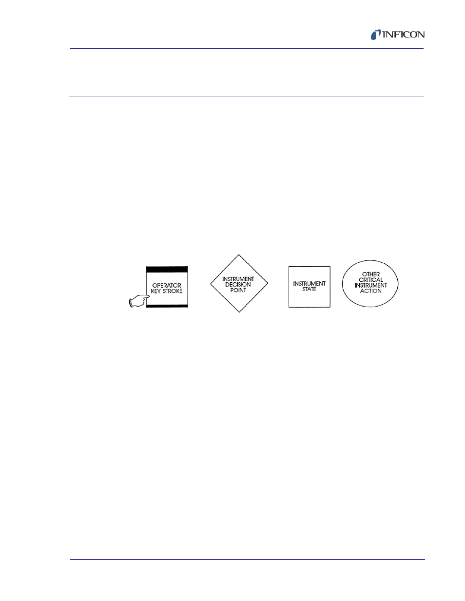
display functions nested within its operation. The following symbols are used in
these flow charts:
Figure 4-1 Symbols Used in Flow Charts
NOTE: The flow diagrams presented, while generally accurate, are not
complete from the standpoint of containing enough information to cover
all possible eventualities. They are presented as a means of quick
overview of the instrument’s operations.