2 xtc/2 display description – INFICON XTC/C Thin Film Deposition Controller User Manual
Page 40
2 - 12
IP
N 07
4-
18
3X
XTC/C - XTC/2 Operating Manual
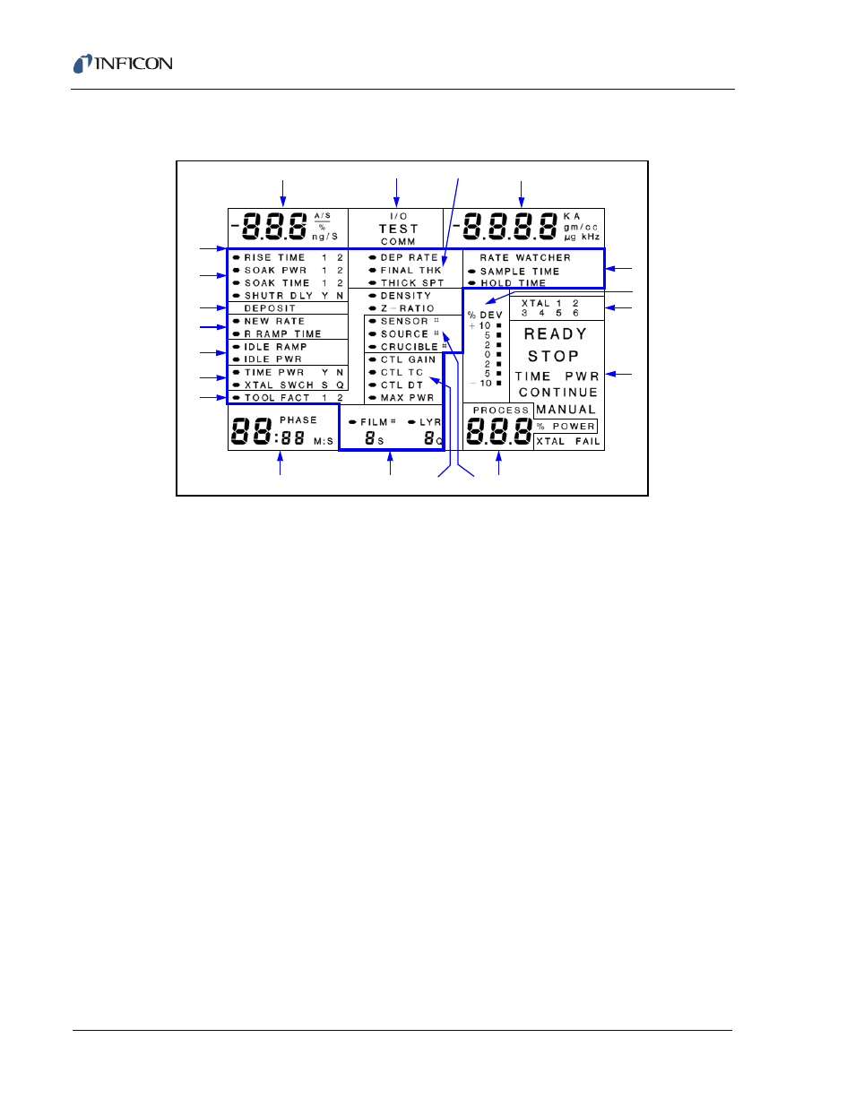
2.4.2 XTC/2 Display Description
Figure 2-7 XTC/2 Display
1— RATE DISPLAY GROUP
Indicates the deposition or etching rate in Å/sec or the version level of the
installed firmware when the LIFE key is pressed and display is in the
Operate mode. When the display is in the Program mode, it is used to
display and enter the values of parameters requiring three significant digits.
2— COMMUNICATIONS & TEST GROUP
A message area that:
a. Indicates that the I/O has been put into external communication control
through the R-15 through R-18 commands.
b. The instrument is in TEST mode, see
.
c. The instrument is sending or receiving an external computer
COMMunication command.
3— DEPOSITION (ETCH) RATE and THICKNESS SUBGROUP
Indicators and annunciators for parameter entry of starting DEPosition
RATE, film’s FINAL THicKness and an intermediate THicKness SetPoinT.
4— THICKNESS and FREQUENCY GROUP
Indicates the deposited (etched) thickness or the active crystal’s frequency
in KHz when the LIFE key is pressed when the display is in the operate
mode. When the display is in the Program mode it is used to display and
enter the values of parameters that require four significant digits.
5— RATEWATCHER SUBGROUP
Indicator annunciator and cursor array for the definition of the RateWatcher
parameters when the display is in the Program mode. Used as an indicator
of the SAMPLE and HOLD deposition substrates when the display is in the
Operate mode.
1
2
3
4
5
6
7
8
9
10
11
12
13
14
15
16
17
18
19
20