5 active oscillator – INFICON XTC/C Thin Film Deposition Controller User Manual
Page 141
5 - 9
IP
N 07
4-
18
3X
XTC/C - XTC/2 Operating Manual
yield theoretically correct results in a time frame that was practical for process
control. To achieve this new level of accuracy requires only that the user enter
an additional material parameter, Z, for the film being deposited. This equation
has been tested for a number of materials, and has been found to be valid for
frequency shifts equivalent to F
f
= 0.4F
q
. Keep in mind that
equation [6]
was
valid to only 0.02F
q
and
equation [7]
was valid only to ~0.05F
q
.
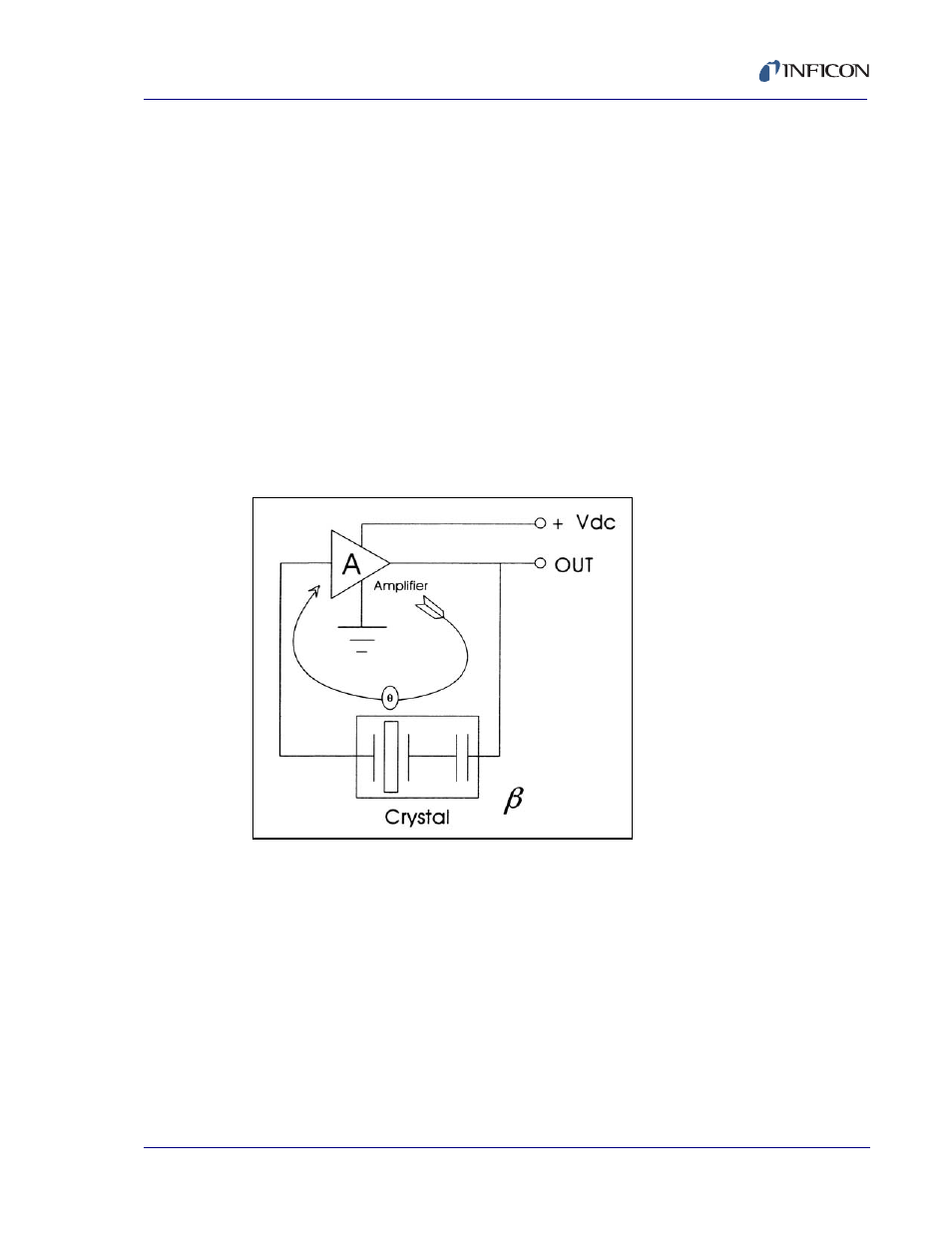
5.5.5 Active Oscillator
All of the instrumentation developed to date has relied on the use of an active
oscillator circuit, generally the type schematically shown in
Figure 5-4
. This
circuit actively keeps the crystal in resonance, so that any type of period or
frequency measurement may be made. In this type of circuit, oscillation is
sustained as long as the gain provided by the amplifiers is sufficient to offset
losses in the crystal and circuit and the crystal can provide the required phase
shift.
Figure 5-4 Active Oscillator Circuit
The basic crystal oscillator’s stability is derived from the rapid change of phase
for a small change in the crystal’s frequency near the series resonance point,
as shown in
Figure 5-5
.