INFICON XTC/C Thin Film Deposition Controller User Manual
Page 43
2 - 15
IP
N 07
4-
18
3X
XTC/C - XTC/2 Operating Manual
15— CRYSTAL FAIL SUBGROUP
Annunciators and cursors used when the display is in the program mode to
determine tolerated levels of crystal performance and subsequent
instrument actions.
a. TIME PWR Y-N — defines the action taken when a crystal fails; see
.
b. XTAL SWCH S-Q — a two parameter data field used with the digits in
the crystal and process subgroup. These are used to set the level of soft
crystal failures tolerated; see
16— POST DEPOSIT SUBGROUP
Annunciators and cursors used to define the source’s post deposition
power levels; see
.
17— RATE RAMP SUBGROUP
Annunciators and cursors used to define a change in deposition rate during
the deposit state; see
.
18— DEPOSIT STATE INDICATOR
Annunciator used to indicate that the instrument is executing the deposit
state of the active film; see
19— PRE DEPOSIT SUBGROUP
Annunciators and cursors used to define the predeposition source
conditioning when the display is in the Program mode.
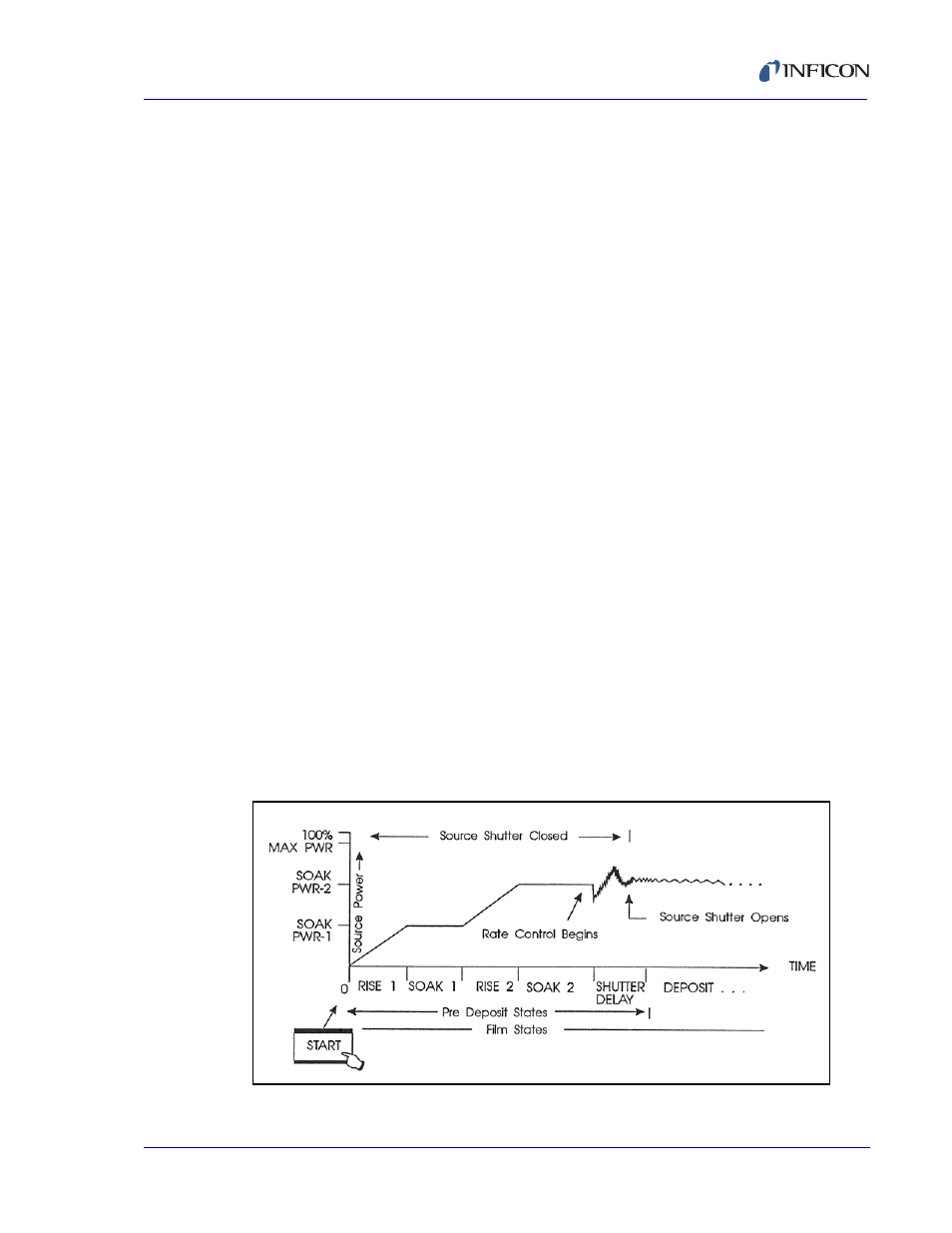
a. RISE TIME 1-2 — defines the length of the rise 1 (2) state.
b. SOAK PWR 1-2 — defines the power level(s) of the
soak 1 (2) state.
c. SOAK TIME 1-2 — defines the length of the soak 1 (2) state.
These parameters, together, define a two step source power profile with
linear changes in power between levels as shown graphically in
.
d. SHUTR DLY Y-N — executes (Y) or skips (N) the shutter delay phase;
see
.
Figure 2-8 Source Power Level Profile