INFICON Cygnus Thin Film Deposition Controller User Manual
Page 106
5 - 2
IP
N 07
4-
37
9-
P1
K
Cygnus Operating Manual
The following pin assignments should be used when constructing a cable:
The port incorporates hardware flow control via Request to Send / Clear to Send
(RTS/CTS) and Data Terminal Ready / Data Set Ready (DTR/DSR) signaling.
Request To Send (RTS) . . . . . . . . . . The instrument informs the host it is ready to
receive a character by asserting the RTS
signal. It lowers the signal when the receive
buffer is full.
Clear to Send (CTS). . . . . . . . . . . . . The host informs the instrument it is ready to
receive a character by asserting the CTS
signal. The host should lower the signal if its
receive buffer becomes full and raise the
signal when it can receive data again. This
signal has an internal pull up in the
instrument. Therefore, if left disconnected
the instrument will assume the host is always
capable of receiving data (no flow control).
Data Terminal Ready (DTR) . . . . . . . The instrument informs the host that it is
powered up and able to communicate by
asserting this signal.
Data Set Ready (DSR) . . . . . . . . . . . The host informs the instrument that it is able
to communicate. The instrument will ignore
all incoming data if this signal is de-asserted.
This signal has an internal pull up in the
instrument. Therefore, if left disconnected
the instrument will assume the host is always
able to communicate.
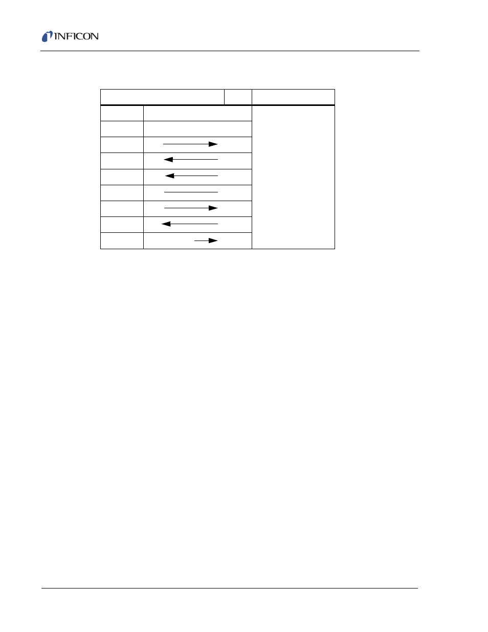
Table 5-1 RS-232C Cable Pin Assignments
Cygnus (9-Pin D-sub)
Host
Pin 1
(Not used)
The 760-406-P1
RS232 Loop-back
connector provided in
the ship kit connects
the following pins:
2 to 3,
4 to 6 and
7 to 8.
Pin 2
TXD
RXD
Pin 3
RXD
TXD
Pin 4
DSR
DTR
Pin 5
GND
GND
Pin 6
DTR
DSR
Pin 7
CTS
RTS
Pin 8
RTS
CTS
Pin 9
GND (Shield)