4 foh & mons sharing sd series racks (opto v221), Chapter 3 - connections & multi console setups – DiGiCo SD Series User Manual
Page 95
Chapter 3 - Connections & Multi Console Setups
3-5
will have full control of the rack. If you set a rack to be in receive only mode, then that console will not be able to make changes to
mic amp gain etc, but will “see” the changes made by the other console. This is necessary for Gain Tracking to function. The third
option is isolate, and when in this mode, the console will not be able to make changes, nor see changes made by someone else.
Gain tracking will not work if the rack is set in isolate mode.
To set a console as the master controller for the racks : In the Audio IO Panel, select the appropriate stage rack. Press the Splits
and Sharing button. In the section titled Selected Rack, press the shared button. It will default to the Isolate setting. Then press
the full control button. A warning will remind you that going into full control may affect the live audio.. then press Yes. If required,
repeat this process for the second stage rack.
To set racks to be in receive only mode : In the Audio IO Panel, select the appropriate stage rack. Press the Splits and Sharing
button. In the section titled Selected Rack, press the shared button. It will default to the Isolate setting. Then press the receive
only button. A warning will remind you that your session will change to correctly reflect the actual settings on the rack.. then
press Yes. If required, repeat this process for the second stage rack.
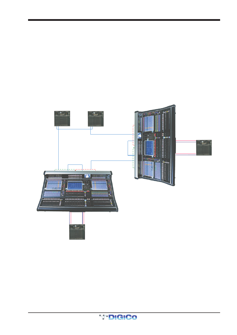
3.2.4 FOH & Mons sharing SD Series Racks (Opto V221) ............
CONNECTION WITH OPTICAL FIBRE
using SD Series Racks on Optocore V221
FOH
OPTO ID 1 and 2
Audio Sync = Optocore
MONITORS
OPTO ID 3 and 4
Audio Sync = Optocore
OPTO A
RACK OPTO ID 11
RACK OPTO ID 12
UP TO 14
SD SERIES
RACKS ON
ONE LOOP
OPTO A
OPTO B
OPTO A
O
P
T
O
B
O
P
T
O
A
OPTIONAL
REDUNDANT
LOOP
OPTO A
OPTO A
OPTO B
OPTO B
OPTO B
OPTO B
ENGINE A
ENGINE B
E
N
G
IN
E
B
E
N
G
IN
E
A
OPTIONAL
LOCAL RACK
AUX MADI
IN/OUT
ENGINE A
MADI PORT 2
IN/OUT
ENGINE B
MADI PORT 2
IN/OUT
MAIN MADI
IN/OUT
OPTIONAL
LOCAL RACK
AUX MADI
IN/OUT
ENGINE A
MADI PORT 2
IN/OUT
ENGINE B
MADI PORT 2
IN/OUT
MAIN MADI
IN/OUT
It is possible for up to 5 DiGiCo consoles to share the inputs from remote stage SDRacks using optical fibre cables. It is also
possible for the output cards in the SDRacks to be allocated to the consoles on a card by card basis.
The following example describes how to set up 2 consoles with a pair of stage racks in a Front of House & Monitors configura-
tion. The connections that should be made are shown in the diagram, as follows.
The fibre optic cables connect between each device on the optic loop, and connect an “A Port” to a “B Port”. You should not
connect the optic cables in A-A or B-B configurations. The cables connect between each device to form a closed loop. This is
necessary for the redundant loop to operate correctly.
The diagram also shows each console having a local MADI connected SDRack. These are connected using pair of BNC MADI
Cables between one of the MADI ports on the console and the Main MADI ports on the SDRacks. Additional redundant MADI
cables can be used, connected the redundant MADI ports on the console to the Aux MADI Ports on the SDRack.