4 matrix channels specific functions, 6 channel signal processing, 1 channel filters – DiGiCo SD Series User Manual
Page 24: 2 input channel eq, Aux mix presets, Aux to rotary, Channel filters, Copy levels from, 4 matrix channels specific functions -17, 6 channel signal processing -17
Chapter 1 - Channel Types
1-17
Pressing aux to rotary assigns control of all input channel’s auxiliary sends to the top available encoder row beneath the
Channel Strip panel.
The purple copy levels from buttons also affect the sends to that aux bus from all of the Input channels. The buttons list can be
scrolled using the scroll bar on the right. These buttons are used for universally setting the aux send levels:
Off sets the level to off and 0dB to 0db. fader sets each Input channel’s aux send level to match the level of its channel fader.
The remaining copy levels from buttons copy a different set of Input channel aux send levels to that aux send.
Note that when a copy levels from button has been pressed, send levels can still be individually readjusted
within the Input channel.
Touching the mix presets button (below the copy mix levels from list) opens the Aux Mix Presets display, where you can
store and recall presets of an aux send's parameters for all input channels, using the standard presets procedure, detailed in
Section 2.
1.5.4 Matrix Channels Specific Functions ....................................
As the Matrix channel input signals are defined within the Matrix inputs display, there is no input selection available within the
Matrix channel.
1.6 Channel Signal Processing
Each channel type contains similar signal processing functions, including EQ and dynamics. Input channels also have high-pass
and low-pass filters. Pressing on each of these areas of the channel strip will open the relevant signal-processing display.
1.6.1 Channel Filters ......................................................................
(All SD input channels and on SD8,9,11 output channels)
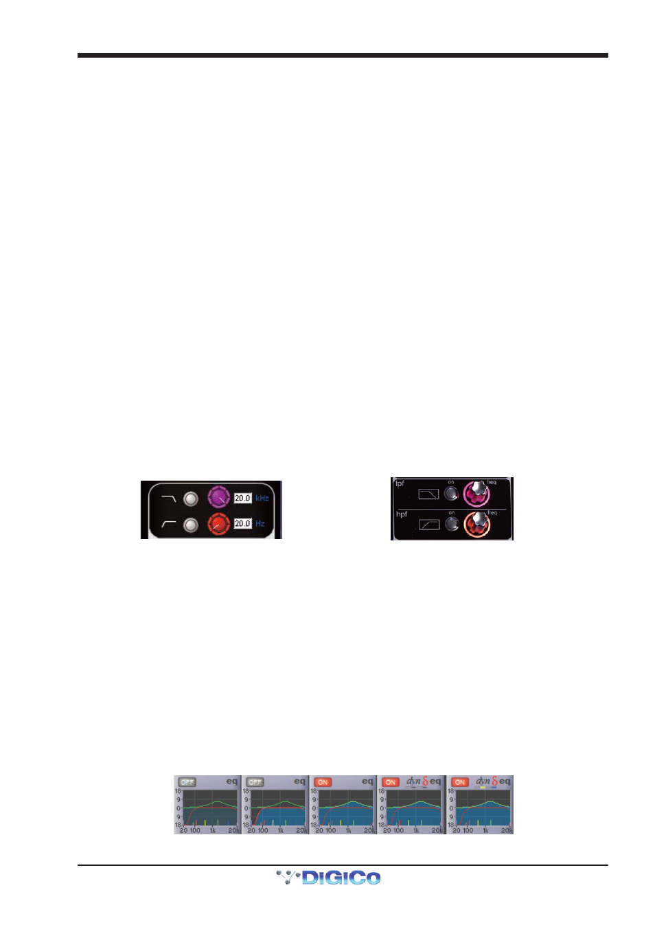
The filters section of the channel-strip is located below the input section of each input channel. It consists of two frequency pots,
each with its own on/off button and a display of the filter’s cutoff frequency (the -3dB value) in Hertz. The on/off buttons are grey
to indicate that the frequency band is off, and red to indicate that it is on. The low-pass filter is at the top and the high-pass filter is
at the bottom, and both have a roll-off of 24dB per octave. The filters directly follow the input section in the signal chain.
The filters area is replicated at the top of the EQ/filters display, accessed by touching the EQ area of the channel strip. The filter
can be configured using the dedicated filter encoders and buttons at the top of the channel worksurface controls:
A graphic representation of the filters is included in the EQ graph located below Insert A in the channel strip, described below.
The red line in the graph represents the current filter settings.
Note that the filters section of the input channel strip may be hidden behind channel meters. In this case,
moving the filter encoders will cause them to be displayed momentarily. To hide the meters and retain a
permanent display of the filter controls, press the assign down button, located to the left of the encoders
above the screen.
1.6.2 Input Channel EQ ..................................................................
The SD input channel EQ has four bands, each of which can be made dynamic. The four EQ bands are colour coded: Blue for HF,
green for HMF, yellow for LMF and red for LF. The in-channel display is located below Insert A and consists of a graphic
representation of the current EQ and an on/off button. The button is grey to indicate that the EQ is off, and red to indicate that it is
on. The green line in the graph represents the frequency response of the EQ, and the red line represents the response of the
filters – each line goes bright to indicate that it is on. The extent and brightness of the clouded area in the bottom half of the graph
also indicates which elements are on. The central frequency of each band is displayed by small lines in the band colours, along
the bottom of the graph.
EQ and filters
both off
EQ off,
filters on
EQ on,
Filters off
Dynamic EQ on
bands 2+4, with
both bands off
Dynamic EQ on
band 2+4, with
both bands on