8 graphic eqs menu, 1 graphic eq panel, 2 ganging graphic eqs – DiGiCo SD Series User Manual
Page 71: Build gang, Graphic eq, 8 graphic eqs menu -37, 1 graphic eq panel -37, 2 ganging graphic eqs -37, Chapter 2 - the master screen
Chapter 2 - The Master Screen
2-37
2.8 Graphic EQs Menu
2.8.1 Graphic EQ Panel .................................................................
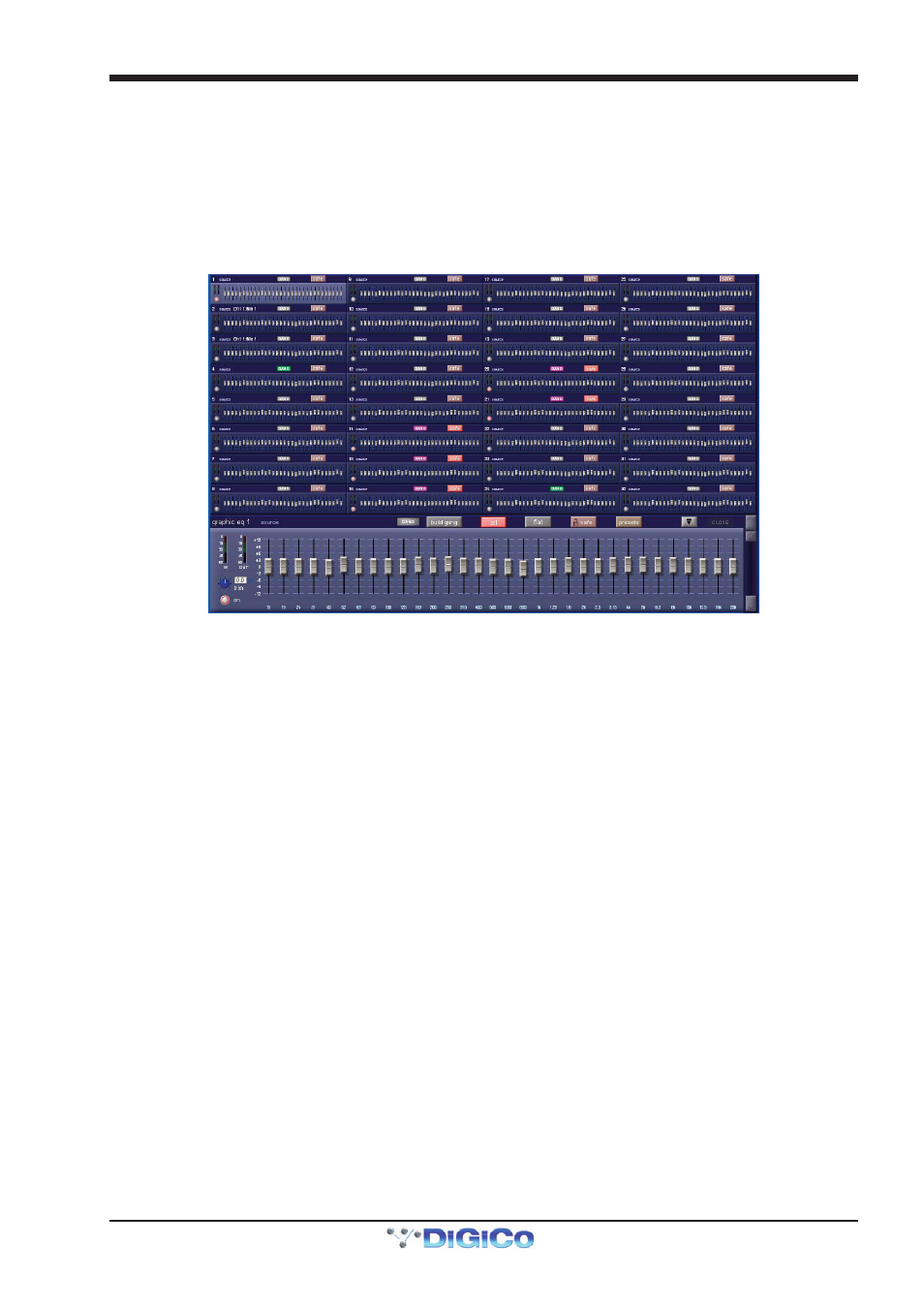
Touching the Graphic EQs menu opens a display of the console’s graphic EQs. This display allows all of the available 32-band
graphic EQ’s to be configured. Graphic EQ’s can be assigned to the inserts and outputs of all four channel types, and can also
feed the input of an input channel. Graphic EQ routing is done via the channel routing pages, and is not accessible from the master
Graphic EQs display.
The display consists of miniature representations of all available graphic EQ’s, one of which is also shown expanded in the bottom
of the display:
The settings on each graphic EQ are accessed via the expanded display, though some settings can also be adjusted in the
miniature display. Touch any of the graphic EQs to assign it to the expanded display. The EQ assigned to the expanded display
can also be scrolled using the scroll bar to the right of the expanded display. The EQ currently assigned to the expanded display is
indicated in the top left-hand corner of the expanded display, along with indication of the EQ’s source. The miniature display can
be opened and closed by pressing the expand button (a down-arrow when opened, and an up-arrow when closed) to the left of
the expanded EQ close button.
The left-hand side of the expanded display includes metering of the EQ’s IN and OUT signals, a ±18dB gain trim pot with value
indication to its right, and an on button which is ringed red to indicate that the EQ is on. Touch the trim pot to assign it to the
Touch-Turn encoder. To the right of these controls, the 32 EQ band faders are displayed. The label located beneath each fader
indicates the frequency of each band in Hertz, and the gain scale associated with each line on the display is indicated to the left
of the lowest band. Each band can also be altered within the miniature display.
2.8.2 Ganging Graphic EQs ...........................................................
The grey GANG and build gang buttons above the band faders are used for ganging together different graphic EQ’s. When EQs
are ganged, their band faders, on buttons and trim pots are locked together.
Note that ganging of faders is relative: EQs can have different shapes when they are ganged, and each EQ
will move by the same amount when a band is adjusted.
Note that if faders are moved within the miniature display, any other EQs ganged to them will also move.
When a set of Graphic EQs are inserted on a stereo or surround channel, those EQ units are automatically ganged together, and
are then automatically unganged when the insert route is removed.
Note that it is the Insert Return routing, not the Insert Send routing, which gangs EQ units.
To start building a gang manually, touch one of the graphic EQs to be included in the gang to assign it to the expanded display, and
touch build gang. The button turns red to indicate that it is active. The GANG button to its left will also become coloured, indicat-
ing that it is included in the gang being built. To add further EQs to the gang, touch the relevant small Graphic EQ display on the
other Graphic EQs to be included, and they will change colour to match the expanded EQ’s GANG button. To deselect any EQs
from the gang, touch their GANG buttons again and they will return to grey. Touch the build gang button to complete the ganging
process. EQ gang assignments can be adjusted by reselecting the build gang button.
Note - To temporarily isolate a Graphic EQ band from a gang, press and hold the mute button above the
band's fader and then make the adjustment to that fader - this move will only be made to that band on the
Graphic EQ that you are currently adjusting.