9 copy audio, Copy audio, Listen source – DiGiCo SD Series User Manual
Page 83: Listen to copied audio, Set listen source, 9 copy audio -49, Chapter 2 - the master screen, Setting up the system
Chapter 2 - The Master Screen
2-49
2.13.9 Copy Audio ..........................................................................
The Copy Audio Matrix, located in the Setup Menu, has been designed to serve 2 purposes:-
1.
To provide a flexible system for routing input sources from multiple racks to a recording system.
2.
To route inputs from one rack to the outputs of another rack without using up console processing resources.
Any input socket connected to a console port can be copied multiple times to any output port socket. One of these “copies” can
be nominated as your “Listen Source” for when Listen to Copied Audio is activated.
It is also possible to place a copied input socket in “Listen Safe” so that when Listen to Copy Audio is activated, the original
source will be heard rather than the copy source.
Copy Audio settings are not snapshottable and remain constant throughout a session unless they are manually changed by the
user.
Setting up the system
In Audio IO, conform all your ports, make any required Optocore output allocations and map your system.
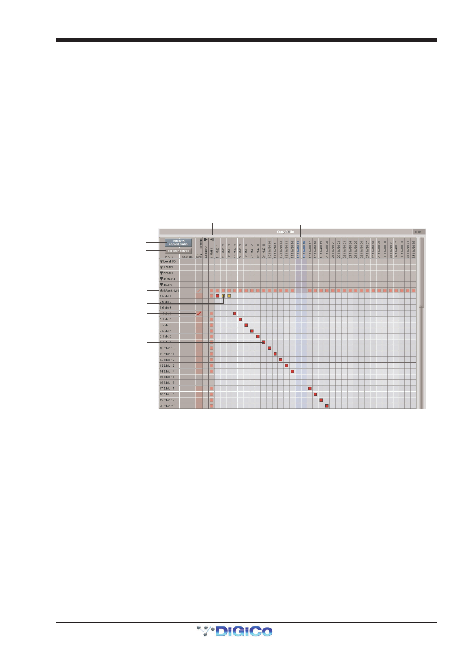
Listen To Copied Audio
Text/Shading in blue
indicates output socket
unavailable
Set Listen Source
Expanded view of rack inputs
Red square indicates copied
and set as the Listen Source
Red tick indicates socket
is in Listen Safe Mode
Orange square indicates copied
but not set as the Listen Source
Expanded view of rack outputs
Open the Master Screen / Setup / Copy Audio panel and you will see the collapsed matrix with input ports listed down the left side
and output ports across the top.
The input port list on the left shows all available input ports that have been configured in Audio IO including Local IO, MADI and
Optocore connections. Touching on any of these ports will expand the list to show the individual sockets. If a socket has been
routed into an input channel, the channel name will be shown in the “Channel” column.
The output port list across the top shows all available output ports that have been configured in Audio IO. When expanded, any
output socket that is already in use or is not allocated to your console is shown in blue and its column highlighted. Existing routes
from channels/busses cannot be overwritten in Copy Audio.
If a port is expanded, touching anywhere in the sockets list will collapse that port.
To make a copy route, expand an input port and output port and touch/drag on the grid. You will see the selected cells turn red.
This first copy, by default, is defined as your Listen Source. Any subsequent copies of the same input socket are shown as
orange cells. You may copy an input socket to as many locations as you wish but only one can be defined as your listen source.
You can change the defined Listen Source by first pressing the “Set Listen Source” button in the top left corner of the panel
and then touching on cell in the matrix. This cell will turn red and any previously selected listen source cell will turn orange.
If you have used the “Copy Audio To” function in the Audio IO Panel and the open the relevant ports in the Copy Audio panel,
you will see a diagonal line of Red cells between the source port and the destination port.
If an output socket is being used as a copy destination, this will be indicated in the Audio IO page by card socket number showing
red (for a Listen Source) or orange (for a copy). You will also see a red/orange square next to any sockets in use in any channel/
buss output routing panel. Please note the copy routes CAN be overwritten by output routes.