3 port hardware configuration, 4 port control, 5 the socket display – DiGiCo SD Series User Manual
Page 81: 6 socket conforming, Full control, Isolate, Port control, Receive only, Shared, Socket display
Chapter 2 - The Master Screen
2-47
2.13.3 Port Hardware Configuration .............................................
The port is named automatically according to its connection type, as displayed to the right of the ports selection area. However,
the name can be edited by touching the Port Name box or the keyboard symbol to its right, typing the new name into the QWERTY
keyboard which appears, and pressing OK. The type of device connected to the port can be altered by touching the down arrow
next to the Device Type box, located next to the Port Name box, and selecting the appropriate device from the drop-down list
that appears. The physical port being used to connect the device can be altered by touching the down arrow next to the Con-
nection box, to the right of the Device Type box, and selecting the appropriate connection port from the drop-down list that
appears. The current status of the connection is displayed below the Connection box as either connected (in green) or not
connected (in red).
Note that the configuration of the Local I/O port is fixed, so no hardware changes are possible. You can,
however, change the Port Name, the Group Names (relating to name of each physical card) and the Socket
Names (the name of each physical connector on a card).
2.13.4 Port Control .........................................................................
Normally, the input gain, phantom power and pad of each DiGiCo Rack input is controlled remotely from the SD Console. However,
in multi-console systems where Racks are shared between two DiGiCo consoles with MADI Connections, only one of the con-
soles can remotely control these rack settings. With Optocore connections any console can have control. Therefore, the level of
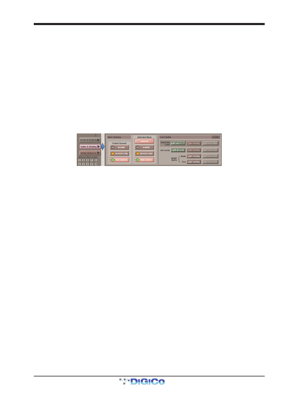
control given to each console must be defined. Control options are displayed in the bottom-right area of the Audio I/O panel when
the Splits & Sharing button towards the base of the panel is pressed:
There are three levels of control:
isolate: The SD Console will not exchange any control data with the rack. This means that the console will neither be able to
adjust rack settings, nor adjust its own settings according to returning control data.
receive only: The SD Console will receive the rack’s existing settings but not send control data back. This means that the
console will not be able to adjust rack settings, but will be able to adjust its own settings according to returning control data.
full control: The SD Console will receive the rack’s existing settings and will send control data back. This means that the console
will be able to adjust the rack’s settings and receive tallies back from the rack.
When the Rack port is selected in the main panel, its control can be defined as shared by pressing the Shared button. Individual
racks can also be controlled using the isolate, receive only and full control buttons beneath the Shared button - these buttons
will only affect the selected port.
2.13.5 The Socket Display .............................................................
When a port has been selected from the ports list on the left, the individual connections within that port are displayed in the
Sockets graphic, which makes up most of the rest of the Audio IO display. For Rack or Console ports, each column in the graphic
represents an IO card, and the type of IO card is displayed at the bottom of each column. For the Local I/O port, each row
represents a type of I/O socket.
Each individual socket displays the following information: the current socket name is across the middle, and the socket number
within the card is in the top left-hand corner.
For analogue input sockets, the current gain is at the bottom, and the top right-hand corner displays a red 48 symbol if the socket’s
phantom power is switched on.
For analogue rack output sockets, there is a -10 symbol in the top right-hand corner which is yellow to indicate that the 10dB pad
is switched in, and white to indicate that no pad is present.
For digital inputs the status of Sample Rate Conversion On/Off is displayed.
Touching a socket within the graphic assigns that socket and its card to the area below the graphic for configuration, as de-
scribed below.
The number in the top left corner of an output socket will change colour if the socket is being used by the Copy Audio Function.
2.13.6 Socket Conforming .............................................................
In order to use the rack, the on-screen contents of the rack must match the cards physically installed in the connected rack. There
are two ways of achieving this:
Manual Conforming
Select each card (column) and manually select the appropriate card in the Card/Slot Type drop down menu in the lower section
of the window. Once the correct card type is selected, the card type name at the bottom the selected card will turn green,