All on, Link, Multiband dynamics – DiGiCo SD Series User Manual
Page 28: Chapter 1 - channel types
Chapter 1 - Channel Types
1-21
threshold buttons. The joint input meter is shown in the expanded display, with the same threshold indication. In multiband
channels, each component has its own meter.
The pots within the expanded display are automatically assigned to the worksurface encoders below the screen when the
dynamics panel is expanded, as indicated by the matching coloured rings around the pots and encoders. When in Multiband mode,
each band is assigned to a row of encoders. When Module 2 is also on, it appears in the bottom row of encoders.
Note that if the gate occupies the bottom row of encoders while the multiband compressor is on, the HF
compressor band is not displayed, and the MF and LF bands both shift up a row.
At the top of the expanded display are buttons marked safe, presets and copy to. Touching safe adds the dynamics to that
channel’s list of channel safes. Touching preset brings up the Presets display which can be used to save and recall presets.
Touching copy to will open the copy to panel with the dynamics section pre selected.
If a link button is shown below the input meter, it allows two channels to be linked together. In other words, the other channel's
signal is added to this compressor’s control circuit input, and this channel’s signal is added to the other channel’s control input.
On stereo input channels, the link is always active and the button isn't shown. On stereo output channels, the link button is
available and the link is always between left and right components; it is active by default.
On mono or multiband channels, pressing this button brings up a dynamics link display listing Channels, Groups and Auxes
signal groups in the left-hand side. When one of these signal groups is selected, their available signals are listed in the right-
hand side of the display. Select a signal to link to and close the display.
The link button is ringed red and the linked channel’s number and name is displayed in the box above it to indicate that there is a
link present. To cancel the link, press the button again and deselect the link signal.
Note that when a link channel has no name, the display repeats the channel number.
Beyond the link function, the different modes of each module have completely separate settings: No settings are copied between
them. If you switch from one mode to the other, the settings will be reset to there defaults. The controls specific to each mode of
each module are described below:
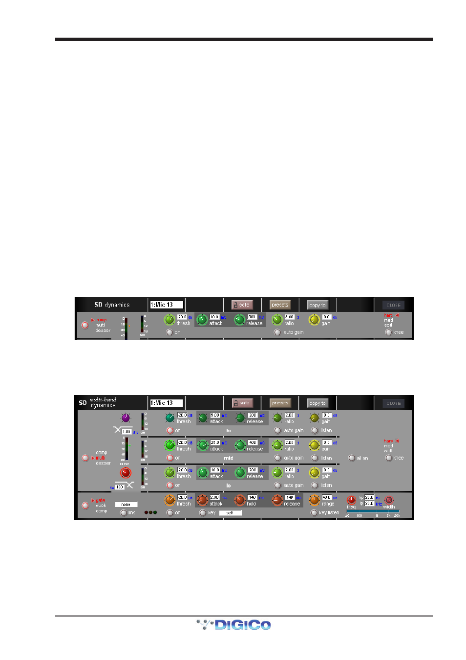
Module 1: Compressor
In Module 1's compressor, threshold, attack, release, ratio and gain controls are provided, each of which function in the
normal way. The compressor has an auto gain function which is switched on by pressing the auto gain button below the ratio
pot. This function automatically adjusts the gain makeup when changes are made to the threshold, thus keeping the compressor
output steady. The threshold knee can be switched between hard, mid and soft using the knee button in the right side of the
module. The gain reduction (GR) meter is duplicated in this display.
Module 1: Multiband Compressor
In Module 1's multiband compressor, each band includes all of the parameters found in the single band compressor. The link
function remains available for the whole compressor, and is not assigned to any band. The bands can be switched on individually
using the on buttons in the left-hand side of each band, or together using the all on button in the display’s right.
The crossover frequency between bands is controlled using the purple and red pots to the left of the hi and lo bands. Each
crossover has a range of 20Hz to 20kHz, and the crossover frequencies are displayed below each pot. Each band can be
auditioned by pressing the listen button below each gain pot.
Important Note: In software versions earlier than V463, when any band is switched off, that band will not pass
audio. In later software versions, bands which are off are bypassed rather than muted.