1 introduction to channel types, 2 channel input setup - common elements, 1 channel strip input area – DiGiCo SD Series User Manual
Page 9: 2 channel delays, Channel types, 1 introduction to channel types -2, 2 channel input setup - common elements -2, 1 channel strip input area -2, 2 channel delays -2, Chapter 1 - channel types
Chapter 1 - Channel Types
1-2
1.1 Introduction to Channel Types
This chapter describes all of the functions available within the SD channel strips. The first two parts of the chapter will examine
the Input/Setup and Output sections of each of the types of channel strip, and the third part will cover the in-channel signal
processing, which functions in precisely the same way on each channel type. Those elements which are common to each
channel type are dealt with first, and then those elements which are specific to a channel type are dealt with separately.
In order to understand this chapter, you will find it helpful to have read the "Getting Started" manual for your console.
1.2 Channel Input Setup - Common Elements
1.2.1 Channel Strip Input Area .....................................................
The channel strip input section is located at the top of the channel strip (shown below for an Input channel). This is where the
channel inputs, snapshot safes, and solo bus feeds are configured. Some basic controls are displayed in the channel strip.
However, most of the input parameters are contained in the channel Setup display, accessed by touching the channel’s input or
filters areas at the top of the screen. The Setup display also contains a number of channel configuration elements.
Note that channels without an external input selected display a simpler input section than that shown here.
Note also that input channels can display a channel meter which hides the input and filters sections of the
channel strip. Press the 'assign' down button to close the meter view.
The large pot at the top of the input area of the main channel strip controls the input level, and can be accessed using the encoder
immediately above the channel strip (SD7,8,10) or using the "quick select" buttons (SD 5, 9,11). For Input channels which have
ADC’s assigned to their inputs, this remotely controls the analogue gain of the mic pre-amp in the I/O rack. For all other input types,
this is a digital level trim. The gain value is displayed to the right of the level pot.
To the left of the pot there is a phase reverse button which is grey when inactive and red when switched in.
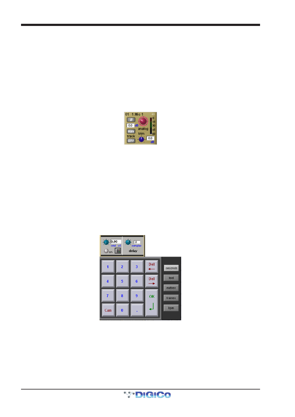
1.2.2 Channel Delays .....................................................................
Delay controls are found in the Setup display. The delay can be switched on using the on button, which is ringed in red to
indicate that it is on. The left-hand blue pot controls the course delay amount in milliseconds. The right-hand blue pot enables fine
adjustments to be made to this amount, measured in samples. Both pots can be assigned to encoders by touching the on screen
control.
It is also possible to enter a specific delay amount using a numeric keypad. To do this, touch the keypad symbol to the right of the
delay on button in the Setup display, select the desired units from the buttons to the right of the number buttons (seconds, feet,
metres, frames or bpm) enter to amount using the keypad, and press OK.
Note that altering the delay units in this keypad display will change them wherever they appear on the
console.