Fibre channel host id address setting, Fibre channel host id address – HP Surestore Disk Array 12h and FC60 User Manual
Page 179
Configuration Switches 179
Inst
alla
tion
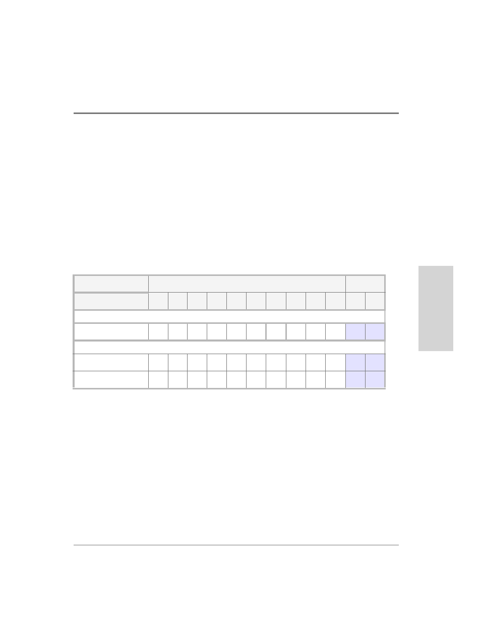
a low range of IDs (0, 1, 2, 3, and 4) and a high range of IDs (8, 9, 10, 11, and 12). (BCCs are
also provided addresses as shown in
). Note that the SCSI IDs do not correspond to
the physical slot number.
The assignment of the SCSI IDs differs depending on whether the enclosure is operating in
full-bus or split-bus mode. When full-bus mode is selected, the low ID range (0 - 4) is
assigned to the even disk slots, and the high range (8 - 12) is assigned to the odd slots. See
. When the disk enclosure is in split-bus mode, the low ID range is assigned to both
the even slots and the odd slots. This is possible because the two busses are isolated within
the enclosure. See
"Selecting Disks for a RAID 0/1 LUN" on page 243
for additional disk
module addressing information.
Fibre Channel Host ID Address Setting
The controller enclosure has two Fibre Channel connections, one for each controller
module. Each controller module communicates with the host through its Fibre Channel
loop connection. Internally the two controllers are connected to a common Fibre Channel
loop. Because they are connected to a common loop, each controller module must have a
unique Fibre Channel Host ID.
The Fibre Channel Host IDs are selected by two separate DIP switches located on the back
of the controller enclosure. See
. Switch Host ID BD1 SW1 selects the address for
Table 25
Disk Slot, Full-Bus/Split-Bus Mode, SCSI IDs
Physical Disk Slot #s
BCC
0
1
2
3
4
5
6
7
8
9
A
B
Full-Bus Mode SCSI IDs
BCC A (or B)
0
8
1
9
2
10
3
11
4
12
14
15
Split-Bus Mode SCSI IDs
BCC-A (Even Slots)
0
-
1
-
2
-
3
-
4
-
15
-
BCC-B (Odd Slots)
-
0
-
1
-
2
-
3
-
4
-
15