IAI America E-Con User Manual
Page 83
75
4. XSEL-R/S/RX/SX/RXD/SXD
4.6 How to Handle XSEL I/O Port Numbers and PLC Addresses
In PLC, the
XSEL
's CC-Link board is set as the remote device station.
The number
of
occupied remote device stations varies, depending on the I/O point setting on the
XSEL
side.
Shown
below is a table describing the relation between the I/O port numbers and PLC by the number
of I/O ports setting (total number of ports used for CC-Link).
(1) In the case that the I/O Point Setting is up to 96 points
(
No. of Occupied Stations: One Station
)
16
000 to 015
RY 0 to F
300 to 315
RX 0 to F
32
016 to 031
RY 10 to 1F
316 to 331
RX 10 to 1F
48
032 to 047
RWw0
332 to 347
RWr0
64
048 to 063
RWw1
348 to 363
RWr1
80
064 to 079
RWw2
364 to 379
RWr2
96
080 to 095
RWw3
380 to 395
RWr3
Note
The ports in gray column show the system domain for the remote device
station on the PLC side, so any of them can not be used as an I/O port.
[
Refer to Section 4
]
(2)
When the number of I/O points is set to 112 or more and 192 or less
(
two stations are occupied
)
I/O Point
Input Port Number on
XSEL
PLC Side
Output Port Number
on XSEL
PLC Side
16 000
to
015 RY
0
to
F 300
to
315 RX
0 to
F
32 016
to
031 RY
10
to
1F 316
to
331 RX
10
to
1F
48 032
to
047 RY
20
to
2F 332
to
347
RX 20 to 2F
64
048
to
063
RY 30
to
3F
348
to
363
RX 30 to 3F
80 064
to
079 RWw0 364
to
379 RWr0
96 080
to
095 RWw1 380
to
395 RWr1
112 096
to
111 RWw2 396
to
411 RWr2
128 112
to
127 RWw3 412
to
427 RWr3
144 128
to
143 RWw4 428
to
443 RWr4
160 144
to
159 RWw5 444
to
459 RWr5
176 160
to
175 RWw6 460
to
475 RWr6
192 176
to
191 RWw7 476
to
491 RWr7
Note
The ports in gray column show the system domain for the remote device
station on the PLC side, so any of them can not be used as an I/O port.
[
Refer to Section 4
]
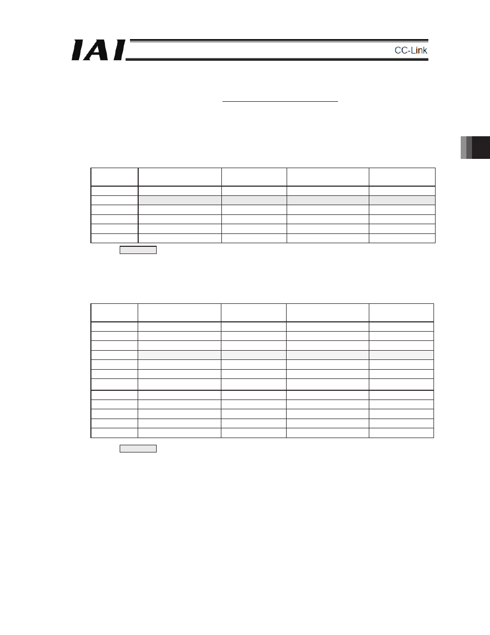
4.6 How to Handle XSEL I/O Port Numbers and PLC Addresses
In PLC, the XSEL’s CC-Link board is set as the remote device station.
The number of occupied remote device stations varies, depending on the I/O point setting on the
XSEL side.
Shown below is a table describing the relation between the I/O port numbers and PLC by the
number of I/O ports setting (total number of ports used for CC-Link).
(1)
In the case that the I/O Point Setting is up to 96 points (one station is occupied)
I/O Point
Input Port Number on
XSEL
PLC Side
Output Port Number
on XSEL
PLC Side
16
000 to 015
RY 0 to F
300 to 315
RX 0 to F
32
016 to 031
RY 10 to 1F
316 to 331
RX 10 to 1F
48
032 to 047
RWw0
332 to 347
RWr0
64
048 to 063
RWw1
348 to 363
RWr1
80
064 to 079
RWw2
364 to 379
RWr2
96
080 to 095
RWw3
380 to 395
RWr3
Note The ports in gray column show the system area for the remote device station on
the PLC side, so any of them can not be used as an I/O port.
[Refer to Section (4)]
(2) When the number of I/O points is set to 112 or more and 192 or less (two stations are occupied)
I/O Point
Input Port Number on
XSEL
PLC Side
Output Port Number
on XSEL
PLC Side
16
000 to 015
RY 0 to F
300 to 315
RX 0 to F
32
016 to 031
RY 10 to 1F
316 to 331
RX 10 to 1F
48
032 to 047
RY 20 to 2F
332 to 347
RX 20 to 2F
64
048 to 063
RY 30 to 3F
348 to 363
RX 30 to 3F
80
064 to 079
RWw0
364 to 379
RWr0
96
080 to 095
RWw1
380 to 395
RWr1
112
096 to 111
RWw2
396 to 411
RWr2
128
112 to 127
RWw3
412 to 427
RWr3
144
128 to 143
RWw4
428 to 443
RWr4
160
144 to 159
RWw5
444 to 459
RWr5
176
160 to 175
RWw6
460 to 475
RWr6
192
176 to 191
RWw7
476 to 491
RWr7
Note The ports in gray column show the system area for the remote device station on
the PLC side, so any of them can not be used as an I/O port.
[Refer to Section (4)]