Fig. 3-1-1, 1) compact type (j type) – IAI America E-Con User Manual
Page 19
11
3. X-SEL-J/K/P/Q/JX/KX/PX/QX
(*1) The CC-Link board installation position is the same as Fig. 3-1-1 for four axes specifications.
(*2) The CC-Link board installation position is the same as Fig. 3-1-2.
(*3) The CC-Link board installation position is the same as Fig. 3-1-3. The CC-Link board installation position for five axes and
six axes specifications are the same as the four axes specification.
(Note): 16 points each for input and output among I/O points are in the system area of the remote device station, therefore, these
points cannot be used.
For details, please refer to “3.1.7 Correspondence between X-SEL I/O port number and PLC address.”
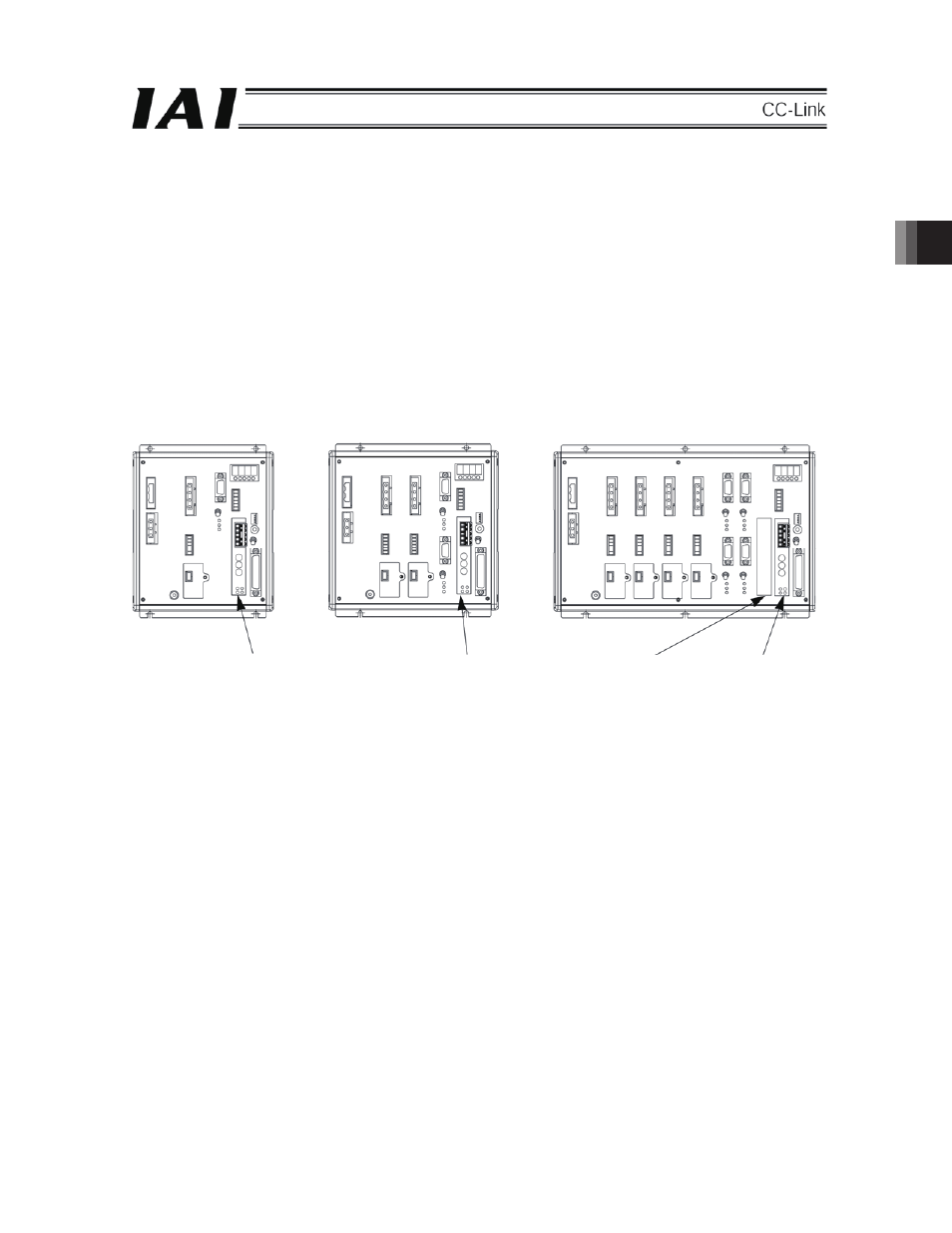
(1)
Compact type (J type)
For single axis
For two axes
For three and four axes
Note: For items of single axis and two axes, a PIO board cannot be installed. For those of three and four axes, an expansion
I/O board
(*1)
can be inserted into the expansion slot.
Fig. 3-1-1
CC-Link board
CC-Link board
Expansion slot
CC-Link board