4 i/o port nos. and corresponding plc addresses – IAI America E-Con User Manual
Page 134
126
8.
ASEL, PSEL, SSEL
7.4 I/O Port Nos. and Corresponding PLC Addresses
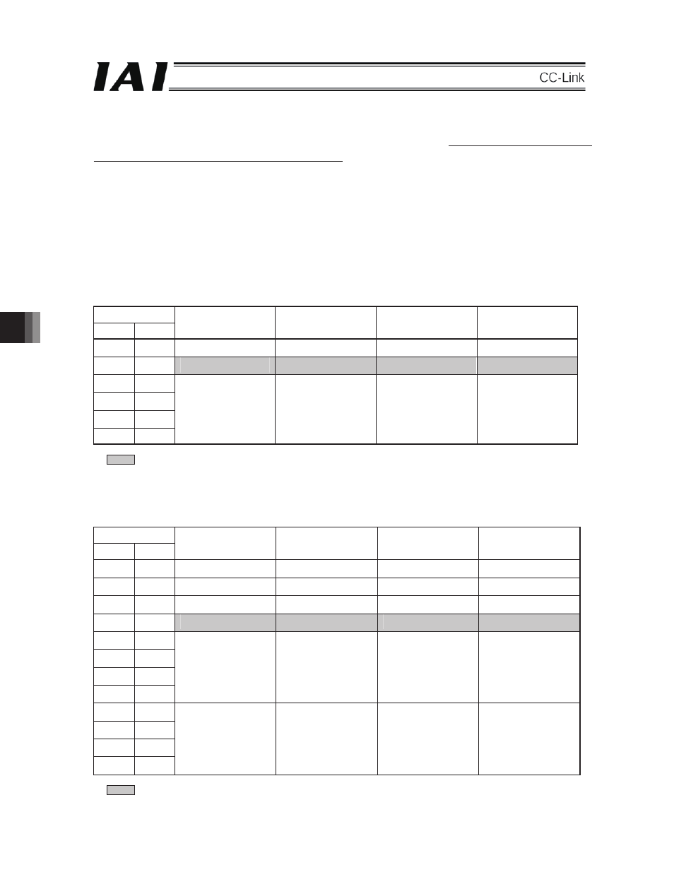
In PLC, ASEL, PSEL or SSEL CC-Link board is set as the remote device station. The number of occupied remote
device stations varies, depending on the I/O point setting on the ASEL, PSEL and SSEL side.
The following table shows the example when I/O parameter No. 1 is set to “0”, No. 16 to “0” and No. 17 to “300” in
the program mode. This shows the relationship between the I/O port Nos. decided by means of the setting of I/O
parameter No 14 and No. 15, and the PLC addresses. The last one word for the occupied remote I/O shows the
system domain for the remote device station, so the corresponding ports can not be used as the I/O ports.
Note: Take whichever is the larger of the point values for I/O Parameter No. 14 and No. 15 and set that same value for both for
No. 14 and No. 15.
(1)
In the case that the I/O Point Setting is up to 96 points:
They are configured as a single remote device (No. of Occupied Stations: One Station)
I/O Parameter
No.14 No.15
DI on the ASEL, PSEL
and SSEL
Side (Port Nos.)
PLC Side
DO on the ASEL,
PSEL and SSEL
Side (Port No.)
PLC Side
16
16
000 – 015
RY
0 – F
300 – 315
RX
0 – F
32 32
016 – 031
RY
10 – 1F
316 – 331
RX
10 – 1F
48
48
032 – 047
RWw0
332 – 347
RWr0
64
64
048 – 063
RWw1
348 – 363
RWr1
80
80
064 – 079
RWw2
364 – 379
RWr2
96
96
080 – 095
RWw3
380 – 395
RWr3
* The ports in gray column show the system domain for the remote device station on the PLC side, so any of them can
not be used as an I/O port.
(2)
In the case that I/O Points setting is larger than 112 and smaller than 192 points:
They are configured as two remote devices (No. of Occupied Stations: Two Stations)
I/O Parameter
No.14 No.15
DI on the ASEL, PSEL
and SSEL
Side (Port Nos.)
PLC Side
DO on the ASEL,
PSEL and SSEL
Side (Port No.)
PLC Side
(16)
(16)
000 – 015
RY
0 – F
300 – 315
RX
0 – F
(32)
(32)
016 – 031
RY
10 – 1F
316 – 331
RX
10 – 1F
(48)
(48)
032 – 047
RY
20 – 2F
332 – 347
RX
20 – 2F
(64) (64)
048 – 063
RY
30 – 3F
348 – 363
RX
30 – 3F
(80)
(80)
064 – 079
RWw0
364 – 379
RWr0
(96)
(96)
080 – 095
RWw1
380 – 395
RWr1
112
112
096 – 111
RWw2
396 – 411
RWr2
128
128
112 – 127
RWw3
412 – 427
RWr3
144
144
128 – 143
RWw4
428 – 443
RWr4
160
160
144 – 159
RWw5
444 – 459
RWr5
176
176
160 – 175
RWw6
460 – 475
RWr6
192
192
176 – 191
RWw7
476 – 491
RWr7
* The ports in gray column show the system domain for the remote device station on the PLC side, so any of them can
not be used as an I/O port.
8
In PLC, ASEL, PSEL or SSEL CC-Link board is set as the remote device station. The number of occupied remote
device stations varies, depending on the I/O point setting on the ASEL, PSEL and SSEL side.
The following table shows the example when I/O parameter No. 1 is set to “0”, No. 16 to “0” and No. 17 to “300” in
the program mode. This shows the relationship between the I/O port Nos. decided by means of the setting of I/O
parameter No 14 and No. 15, and the PLC addresses. The last one word for the occupied remote I/O shows the
system area for the remote device station, so the corresponding ports can not be used as the I/O ports.
Note: Take whichever is the larger of the point values for I/O Parameter No. 14 and No. 15 and set that same value for both for
No. 14 and No. 15.
The ports in gray column show the system area for the remote device station on the PLC side, so any of them can
The ports in gray column show the system area for the remote device station on the PLC side, so any of them can