3 i/o signal assignment, Scon-c – IAI America E-Con User Manual
Page 123
115
7. SCON-C
6.3 I/O signal assignment
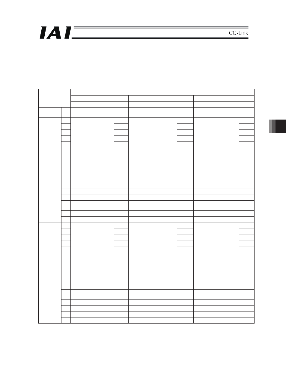
Number of I/O points for SCON:
Input only: 16 points, Output only: 16 points
The following table shows the detailed contents.
There are 6 patterns according to the setting of parameter No. 25 (PIO Pattern selection) of SCON.
For additional, for further information on each signal, refer to the “Operation Manual for SCON Controller.”
Parameter No. 25 setting
Positioning mode (Standard)
Teaching mode (Teaching type)
256 point mode (256 point type)
0 1 2
Classification
Port
No.
Signal Names
Symbol
Signal Names
Symbol
Signal Names
Symbol
0 PC1
PC1
PC1
1 PC2
PC2
PC2
2 PC4
PC4
PC4
3 PC8
PC8
PC8
4 PC16
PC16 PC16
5
Command position No.
PC32
Command position No.
PC32 PC32
6
Teaching Mode Command
(Operation Mode)
MODE
PC64
7
Jog/Inching
selection JISL
Command position No.
PC128
8
Unavailable
+Jog JOG+
Unavailable
9
Forced brake release
BKRL
-Jog
JOG-
Forced brake release
BKRL
10
Operation mode
RMOD
Operation mode
RMOD
Operation mode
RMOD
11
Return to origin
HOME
Return to origin
HOME
Return to origin
HOME
12 *Suspend *STP
Suspend
*STP
Suspend *STP
13 Positioning
Start CSTR
Positioning Start
Position Data Import Command
CSTR/P
WRT
Positioning Start
CSTR
14 Reset RES
Reset
RES
Reset RES
Input
15
Servo ON Command
SON
Servo ON Command
SON
Servo ON Command
SON
0 PM1
PM1
PM1
1 PM2
PM2
PM2
2 PM4
PM4
PM4
3 PM8
PM8
PM8
4 PM16
PM16 PM16
5
Completion position No.
PM32
Command position No.
PM32 PM32
6
Moving Signal
MOVE
Moving Signal
MOVE
PM64
7 Zone
1
ZONE 1
Teaching mode Signal
MODES
Command position No.
PM128
8
Position zone status
RMDS
Position zone status
RZONE
Position zone status
RZONE
9
Operation Mode Status
RMOD
Operation Mode Status
RMDS
Operation Mode Status
RMDS
10
Return to origin end
HEND
Return to origin end
HEND
Return to origin end
HEND
11
Positioning end Signal
PEND
Positioning end Signal /
Position Data Import Command
PEND/
WEND
Positioning end Signal
PEND
12
Operation preparation end
SV
Operation preparation end
SV
Operation preparation end
SV
13 Emergency
stop *EMGS
Emergency
stop *EMGS
Emergency
stop *EMGS
14 Alarm *ALM
Alarm
*ALM Alarm *ALM
Output
15
Battery alarm
*BALM
Battery alarm
*BALM
Battery alarm
*BALM
The symbol with a * mark shows the ON signal in normal condition.
The signal described as “Unavailable” is not controlled (ON/OFF is undefined).
In the case of the incremental encoder, the battery alarm is turned ON (fixed).
7