3 input and output (i/o) – IAI America E-Con User Manual
Page 115
107
6. RCS-C and E-Con
5.3 Input and Output (I/O)
Input and output points for each RCS-C and E-Con are
(1) RCS-C Input only: 8 points, output only: 11 points
(2) E-Con Input only: 10 points, output only 13 points
For further information of each signal, please refer to the “Operation Manual of the
RCS Series ROBO Cylinder Controller RCS-C type” and “Operation Manual of E-Con
Controller.”
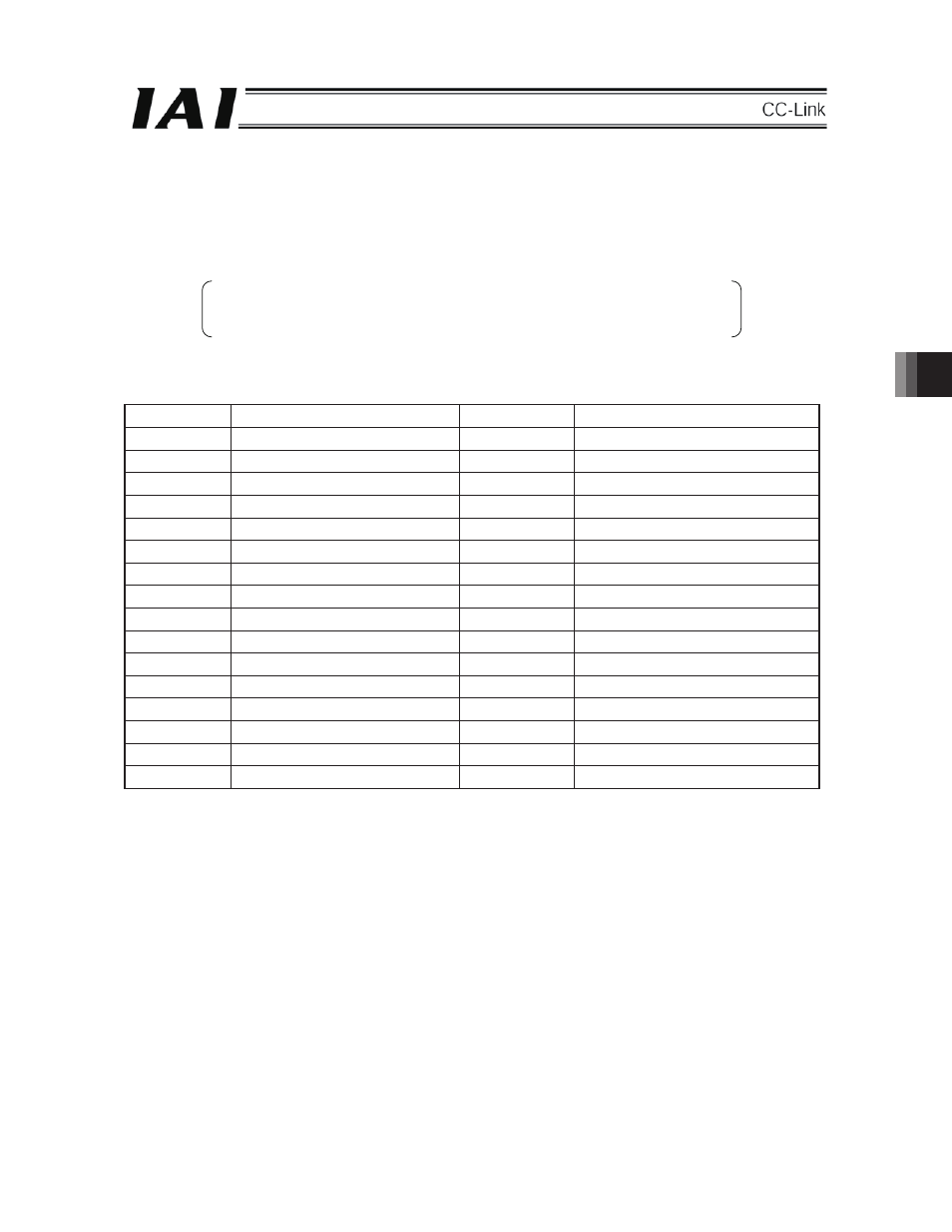
(1)
RCS-C signal assignment
Input port No.
Signal name
Output port No.
Signal name
0
Command position 1
0
Completion position 1
1
Command position 2
1
Completion position 2
2
Command position 4
2
Completion position 4
3
Command position 8
3
Completion position 8
4 Start 4
Positioning
completion
5
Reset
5
Return to origin completion
6 Servo
No. 6
*Zone
7 *
Suspend 7
*Alarm
8 Unused 8
*Emergency
stop
9 Unused 9 Traveling
10
Unused
10
*Battery alarm (Note 1)
11 Unused 11
Unused
(Note 2)
12 Unused 12
Unused
(Note 2)
13 Unused 13
Unused
(Note 2)
14 Unused 14
Unused
(Note 2)
15 Unused 15
Unused
(Note 2)
* The asterisk indicates an always on signal.
(Note 1) These signals correspond to only controllers of the main power sources 100V and 200V.
In the case of 24V specification, ON/OFF is not determined.
(Note 2) In the unused areas, ON/OFF is not determined.
6