IAI America E-Con User Manual
Page 100
92
5. T
abletop Robot TT
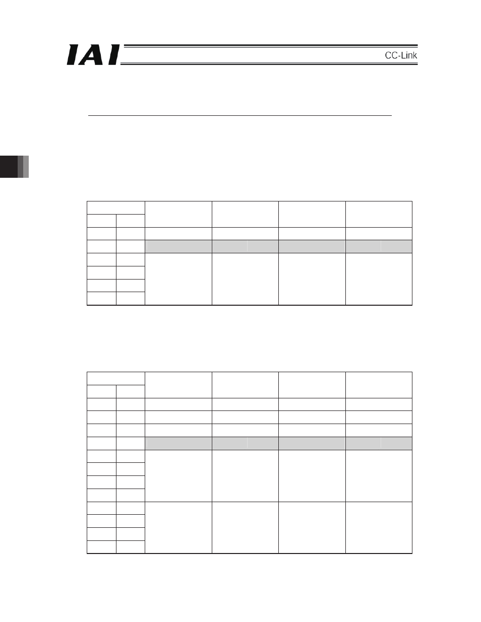
4.5 Correspondence between I/O port numbers and PLC addresses of TT
In the PLC, the CC-Link board of TT is set as a remote device.
The number of occupied stations of the remote device according to the setting of the I/O points on the TT
side changes.
The following table shows the relationships between I/O port numbers and addresses of the PLC according
to the setting of the I/O parameter No. 14 and No. 15.
Note: For I/O parameter No. 14 and No. 15, set the same point for whichever the number is larger.
(1)
When the number of I/O points is set to 96 or less:
Configured as one remote device. (One station occupied)
I/O parameter
No. 14 No. 15
TT side DI
(Port No.)
PLC side
TT side DO
(Port No.)
PLC side
16 16
048 - 063
RY
0
–
F
348 - 363
RX
0
–
F
32 32
064 - 079
RY
10 – 1F
364 - 379
RX
10 – 1F
48 48
080 - 095
RWw 0
380 - 395
RWr 0
64 64
096 - 111
RWw 1
396 - 411
RWr 1
80 80
112 - 127
RWw 2
412 - 427
RWr 2
96 96
128 - 143
RWw 3
428 - 443
RWr 3
* Since the shaded portions are the system areas for the remote device station on the PLC side, they
cannot be used as I/O.
(2)
When the number of I/O points is set to 112 or more and 192 or less:
Configured as two remote devices. (Two stations occupied)
I/O parameter
No. 14 No. 15
TT side DI
(Port No.)
PLC side
TT side DO
(Port No.)
PLC side
(16) (16)
048 - 063
RY
0 – F
348 - 363
RX
0 – F
(32) (32)
064 - 079
RY 10
–
1F 364 - 379
RX 10
–
1F
(48) (48)
080 - 095
RY 20
–
2F
380 - 395
RX 20
–
2F
(64) (64)
096 - 111
RY
30 – 3F
396 - 411
RX
30 – 3F
(80) (80)
112 - 127
RWw 0
412 - 427
RWr 0
(96) (96)
128 - 143
RWw 1
428 - 443
RWr 1
112 112
144 - 159
RWw 2
444 - 459
RWr 2
128 128
160 - 175
RWw 3
460 - 475
RWr 3
144 144
176 - 191
RWw 4
476 - 491
RWr 4
160 160
192 - 207
RWw 5
492 - 507
RWr 5
176 176
208 - 223
RWw 6
508 - 523
RWr 6
192 192
224 - 239
RWw 7
524 - 539
RWr 7
* Since the shaded portions are the system areas for the remote device station on the PLC side, they
cannot be used as I/O.
5