X-sel i/o parameter, B. when only two cc-link boards are used, C. when only one cc-link board is used – IAI America E-Con User Manual
Page 61
53
3. X-SEL-J/K/P/Q/JX/KX/PX/QX
X-SEL I/O parameter
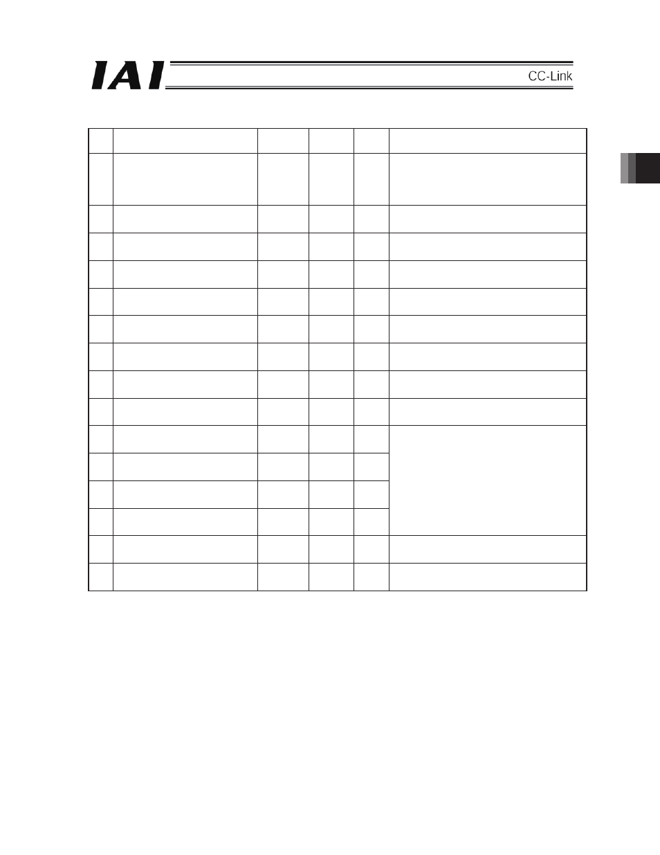
No. Parameter
name
Default
(reference)
Input
range
Setting Remarks
1
I/O port assignment type
1
0 – 20
01
0: Fixed assignment
1: Automatic assignment (Priority: slot 1
)
* The ports only in the continuous installation
range from slot 1 are assigned for safety.)
2
Standard I/O fixed assignment time:
Input port start No. (I/O 1)
-1
-1 – 599
-1
0 + (multiples of 8) (Invalid for negative values)
3
Standard I/O fixed assignment time:
Output port start No. (I/O 1)
-1
-1 – 599
-1
300 + (multiples of 8)
(Invalid for negative values)
4
Expansion I/O 1 fixed assignment
time: Input port start No. (I/O 2)
032
-1 – 599
032
0 + (multiples of 8) (Invalid for negative values)
(Slot next to the standard I/O)
5
Expansion I/O 1 fixed assignment
time: Output port start No. (I/O 2)
332
-1 – 599
332
300 + (multiples of 8)
(Invalid for negative values)
6
Expansion I/O 2 fixed assignment
time: Input port start No. (I/O 3)
016
-1 – 599
016
0 + (multiples of 8) (Invalid for negative values)
7
Expansion I/O 2 fixed assignment
time: Output port start No. (I/O 3)
316
-1 – 599
316
300 + (multiples of 8)
(Invalid for negative values)
8
Expansion I/O 3 fixed assignment
time: Input port start No. (I/O 4)
000
-1 – 599
000
0 + (multiples of 8) (Invalid for negative values)
9
Expansion I/O 3 fixed assignment
time: Output port start No. (I/O 4)
300
-1 – 599
300
300 + (multiples of 8)
(Invalid for negative values)
10 Standard I/O error monitoring
(I/O 1)
0
0 – 5
0
11
Expansion I/O 1 error monitoring
(I/O 2)
2
0 – 5
2
12 Expansion I/O 2 error monitoring
(I/O 3)
2
0 – 5
2
13 Expansion I/O 3 error monitoring
(I/O 4)
2
0 – 5
2
0: Non-monitoring
1: Monitoring
2: Monitoring (Non-monitoring of 24V I/O power
related errors)
(Main application of Ver. 0.55 or later)
3: Monitoring (Monitoring of 24V I/O power
related errors only)
(Main application of Ver. 0.55 or later)
14 Network I/F card remote:
Number of ports used for input
0
0 – 256
0
Multiples of 8
15 Network I/F card remote:
Number of ports used for output
0
0 – 256
0
Multiples of 8
(I/O 1) to (I/O 4) indicate the slot numbers.
b.
When only two CC-Link boards are used
The I/O 2 (expansion I/O 1) slot becomes empty. Accordingly, both the default and set value become “-1” for
the I/O parameter No. 4 and No. 5 and “0” for No. 11 in the table above.
(The above is a case where the installation condition as shown in Fig. 3-2-2 in section 3.2.1 is applied.)
c.
When only one CC-Link board is used
The I/O 2 (expansion I/O 1) and I/O 3 (expansion I/O 2) slots become empty. Accordingly, both the default
and set value become “-1” for the I/O parameters No. 4 to No. 7 and “0” for No. 11 and No. 12 in the table
above.
(The above is a case where the installation condition as shown in Fig. 3-2-1 in section 3.2.1 is applied.)
(Note) When no I/O board is used, it is not required to supply 24V DC to the I/O 24V power connector. In any case of a, b, and c
above, set the I/O parameter No. 10 to “0.”