2 cc-link interface – IAI America E-Con User Manual
Page 130
122
8.
ASEL, PSEL, SSEL
7.2 CC-Link Interface
(1)
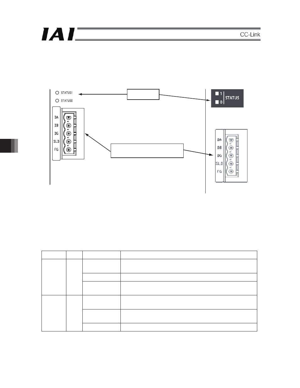
Names of the Parts
z ASELᾨPSEL
z SSEL
(2)
Status LED Indication
The CC-Link board operation status and network status can be obtained using the two LEDs located on the
front surface of the controller.
STATUS 0 LED: CC-Link Communication Status Indication
STATUS 1 LED: CC-Link Communication Setting Error/Communication Error Indication
LED
Color
Indication Status
Indication Description (Meaning)
Illuminating
An error occurs.
CRC Error/Station No. Setting Error/Baud Rate Setting Error
OFF
Normal Communication or Under Reset Operation
STATUS1 OR
Flushing
The station No. and baud rate set values are changed from ones
set at the time of reset cancellation (0.4 sec flashing)
Illuminating
Normal Refresh & Polling Signal Receipt or Normal Refresh Signal
Receipt, after the Network Subscription.
OFF
Before Network Subscription, Channel Carrier Detection Error
Timer Over or Under Reset Operation
STATUS0 GN
Flushing
Note: When the power is injected, the STATUS 1 LED illuminates, which does not mean abnormal.
When the CC-Link communication setting has been performed correctly, the STATUS 1 LED is turned OFF.
Status LED
CC-Link
Communication Connector
8