Pl-1746 section 6 - groups & modes, Introduction to groups & modes, 1 groups & modes – Electro Cam PL-1746 Series User Manual
Page 98
6-1 Groups & Modes
Introduction to Groups & Modes - Using External Inputs to Condition PLS Outputs
Background
In many industrial applications, the action of a machine component such as a glue gun,
solenoid, or pneumatic cylinder is related to an input signal from a limit switch, sensor,
or controller such as a PLC. Input signals are commonly used in two ways:
• Product Present
The device being controlled is allowed to function only if an input signal occurs. A
typical example is gluing, where a photoeye senses the presence of a product imme-
diately before gluing should occur. If the product is not present, the glue gun is not
enabled to turn on at its programmed setpoints.
• Register Marks
The device being controlled must maintain a certain relationship to other devices on
the machine. For example, web converting lines such as disposable diaper machines
usually have several machine sections each performing a different operation on a
continuous web of material. As line speed increases, the phase relationships be-
tween different machine sections are adjusted to compensate for stretching of the
web material. To keep a device synchronized within its machine section, a sensor is
used to detect a registration mark on a component such as shaft or disk. The sensor
signal “resets” the position of the device each revolution, ensuring that the device
operates at the correct position on the web of moving material.
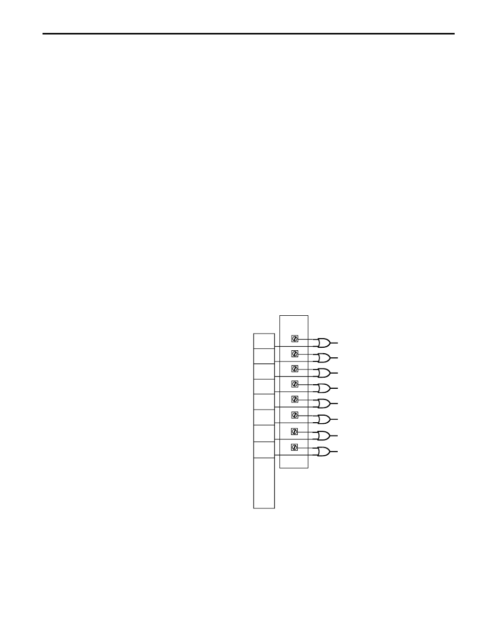
Input Signals
When the Output File word 0 (O:S.0) is not mapped, its low byte, containing group
inputs, the First Cycle Enable input, and the Output Enable input, is or’ed with the input
status terminals, which may be located on a PS-4108 rack (for C01 model) or on the
front panel (C02 & C03 models). When the first word of the SLC output file is mapped,
the group inputs, FCE and output enable inputs are driven directly strictly be the input
terminals.
Input Terminal Block
I0
I1
I2
I3
I4
I5
Group Zero Input
Group One Input
Group Five Input
S = Slot Number
Group Four Input
Group Three Input
Group Two Input
O:S.0/0
O:S.0/1
O:S.0/2
O:S.0/3
O:S.0/4
O:S.0/5
O:S.0/6
O:S.0/7
OR
OR
OR
OR
OR
OR
I6
I7
Output Enable (OE)
First Cycle Enable (FCE)
OR
OR
Groups & Modes
The PL-1746 PLuS Module includes powerful programming capabilities that allow out-
put channels to be linked to input signals from sensors or other devices. Output chan-
nels can be divided into as many as six groups, each of which is associated with a
group input. Each group can then be assigned to operate in one of six modes which
determines the relationship between the channels in the group and the input signals.