Shift count (cont’d), 40 pls functions – Electro Cam PL-1746 Series User Manual
Page 85
4-40 PLS Functions
Shift Count (cont’d)
Screen
MAIN SCREEN
to CONFIG MENU
to SECONDARY SETUP
SHFT
COUNT
Output Channel to be ANDed
Shift Count That Will Enable Output Channel
PGM:0 CHN: 1
SHIFT COUNT: 0
To select the output's channel, program, and shift count, use the numeric keys and
ENT, or use the INC and DEC keys.
Input Window
A bit is set in Position “0” of the shift register when the Product Present Input (Terminal
IO of the pluggable input header) is energized. A Shift Window is provided to limit the
portion of revolution during which the signal will be accepted from Terminal IO. A bit is
set in the Shift Register only if Terminal IO becomes energized within that window.
Description
The shift register is a form of electronic memory that sets a “bit” in the zero count of the
register when a signal is applied to Terminal IO. Afterwards, each time the position
passes the point programmed as the SHIFT POSITION, the register “shifts” the bit to
the next higher count. The bit passes along the shift register until, on the 256th shift, the
bit is erased.
An output channel can be ANDed with any count in the shift register, so that the chan-
nel is enabled only when a bit appears in that count. In this way, output channels can be
enabled up to 255 revolutions after Terminal IO is energized.
• ANDing an output channel with Count “0” is the same as turning Shift Register ANDing
off. The shift register will have no affect on channel operation.
• Any number of output channels can be ANDed to a single shift register count.
• Shift Register ANDing, Input ANDing, and Motion ANDing can be combined for any
given output channel.
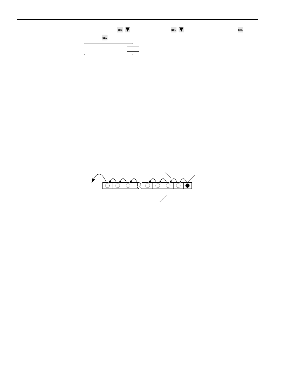
255 254 253 4 3 2 1 0
Bit shifts up once each time
the Shift Position is passed
Zero bit is set if Product
Present (Terminal IO) is
energized within Shift Window
Output channels can be ANDed
with any Shift Register count
Bit is erased
on last shift
Count: