Interrupt enable, Interrupt level, Input status (cont'd) – Electro Cam PL-1746 Series User Manual
Page 57: 12 pls functions
4-12 PLS Functions
Interrupt Enable
Backplane
PL-1746 Function Name
SLC 500
Mapping Read/
Valid Range for Data
File
Index
Write
Address
Number
Capability
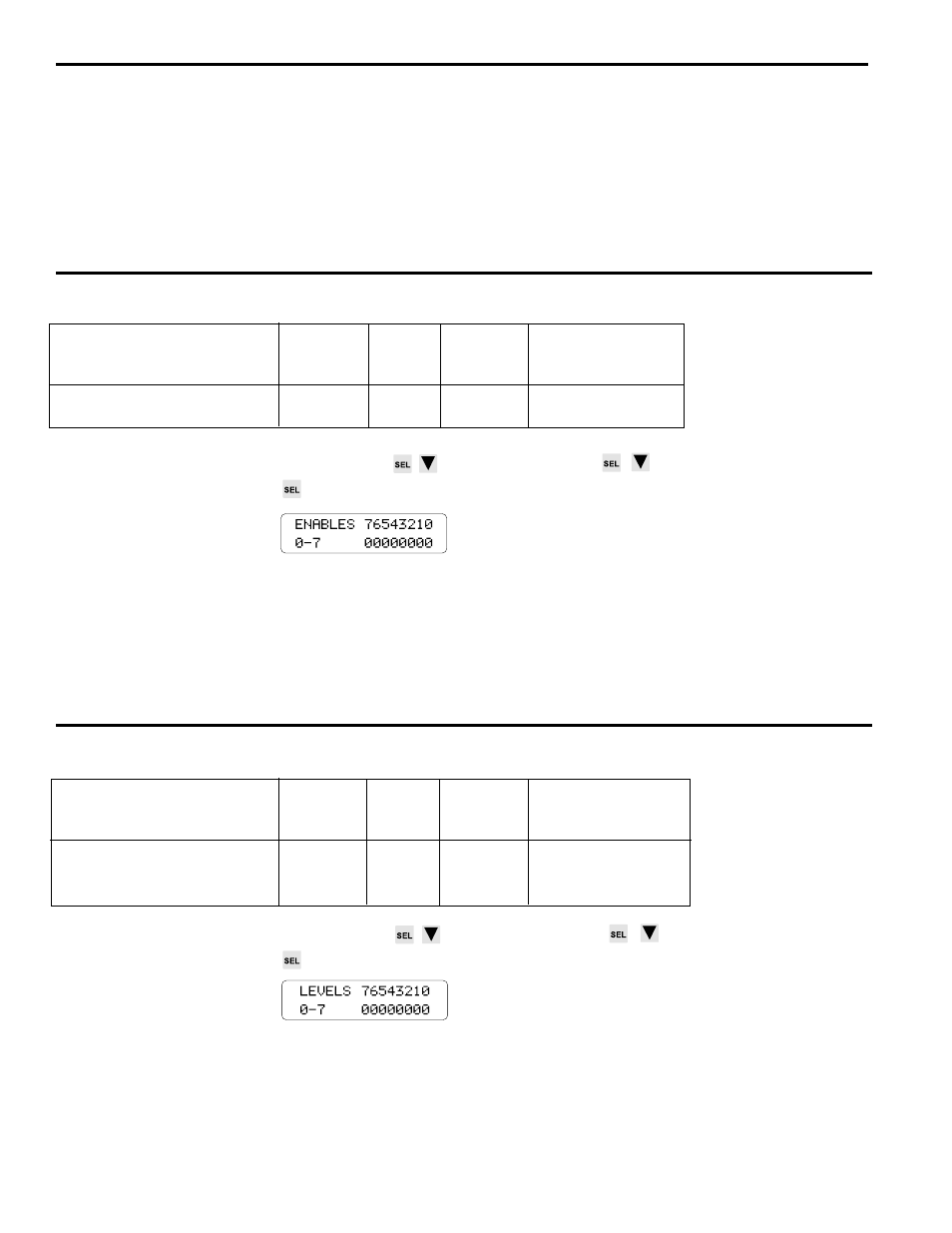
Interrupt Enables
M0:S.132-
392-
R/W
0=Disabled
Channels 0-31, 1bit/channel
M0:S.133
394
1=Enabled
Screen
MAIN SCREEN
to INTERRUPT MENU
to INTERRUPT ENABLE REGS
Use the SEL key to select a set of eight channels, then the left or right arrow keys to
select the enable bit for an individual channel. Use the SEL key to toggle that channel's
bit.
Description
Setting a bit to one will enable that channel to cause an interrupt to the SLC-500 ladder
program when one active transition occurs. See "INTERRUPT LEVEL" for more infor-
mation about transitions.
Interrupt Level
Backplane
PL-1746 Function Name
SLC 500
Mapping Read/
Valid Range for Data
File
Index
Write
Address
Number
Capability
Interrupt Levels
Channels 0-31, 1bit/channel
M0:S.128-
384-
R/W
0= Rising Edge
M0:S.129
386
1= Falling Edge
Screen
MAIN SCREEN
to INTERRUPT MENU
to INTERRUPT LEVEL REGS
Use the SEL key to select a set of eight channels, then the left or right arrow keys to
select the level bit for an individual channel. Use the SEL key to toggle that channel's
bit.
Description
This screen shows which transition of each output channel is selected to generate an
interrupt to the SLC-500 ladder program. Setting a bit to zero will select the zero to one
transition of the specified output channel. Setting a bit to one will select the one to zero
transition of the specified ouput channel.
Input Status (cont'd)
Description
The input status screen displays the Logic Inputs status of the group inputs (0-5), first
cycle enable (6), and output enable (7).
The SLC-500 writes a "1" to activate an input in the Logic Inputs word (O:S.0).
The Logic Inputs Status Register (M0:S.25) contains the current state of the hardware
inputs from the rack OR'ed with the corresponding bits O:S.0, but when O:S.0 is mapped,
the Logic Inputs Status Register only contains the bits from the PS-4108 rack or the
inputs on the front of the C02/C03.