Resolver installation, 7 installation, Cable for resolver with cannon connector – Electro Cam PL-1746 Series User Manual
Page 17: Cable for encoder with terminal strip connections
2-7 Installation
SH
BK
WT
BK
RD
BK
GR
SH
BK
WT
BK
RD
BK
GR
A
B
C
D
E
F
G
H
J
K
X
X
X X
X
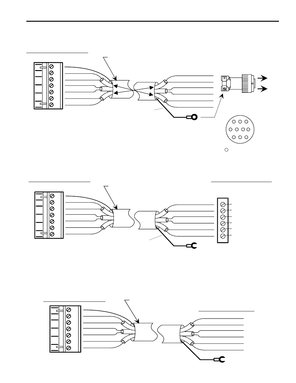
Resolver Installation
Green
White
Shield
Black
Black
Red
Black
Pin A - Black
Pin D - Red
Pin E - Black
Pin F - White
Pin B - Green
Pin C - Black
Connector - Controller End
Cable Type:
3 individually shielded pairs, 22 gauge
Shield
(see note below)
Front View
(pin out)
= Not Used
Shielding Note: Resolver cables made after 3-2-93 have a ring lug on a black shield wire at
the resolver end. The ring lug should be attached to one of the resolver connector strain relief
screws to protect against static discharge through the resolver cable. In some installations,
it may be advisable to disconnect the ring lug to prevent ground loops through the cable shield.
Consult Electro Cam if electrical noise problems are suspected.
Cable for Resolver with Cannon Connector
PT# PS-5300-01-XXX (XXX = Length in Feet)
Cable for Stainless Steel Resolver with Terminal Strip Connections
PT# PS-5300-02-XXX (XXX = Length in Feet)
Connector - Controller End
Connector Inside Resolver
(cable is stripped and tinned at
both ends)
Shielding Note: This type of resolver cable will have a spade lug connected to the shield at the resolver end. The lug should
be attached to the grounding stud on the cover plate of the resolver. In some installations, it may be advisable to disconnect
the lug to prevent ground loops through the cable shield. Consult Electro Cam if electrical noise problems are suspected.
Cable Type:
3 individually shielded pairs, 22 guage
Shield
(see note below)
White
Shield
Black
Black
Red
Black
Green
White
Black
Black
Red
Black
Green
Shield
BLK (P/W) WHITE
WHITE
BLK (P/W) RED
RED
BLK (P/W) GREEN
GREEN
Shield
IMPORTANT! Each black wire must be
attached adjacent to its paired colored wire.
IMPORTANT! Each black wire must be
attached adjacent to its paired colored wire.
SH
BK
WT
BK
RD
BK
GR
Cable for Encoder with Terminal Strip Connections
PT# PS-5300-02-XXX (XXX = Length in Feet)
Connector - Controller End
Cable Type:
3 individually
shielded pairs, 22 guage
White
Shield
Black
Black
Red
Black
Green
Green
Red
Black
Black
White
Black
Shield
Connections to Encoder
A
B
Z
+24V
GND
GND