Output groups, 20 pls functions – Electro Cam PL-1746 Series User Manual
Page 65
4-20 PLS Functions
Output Groups
Backplane
PL-1746 Function Name
SLC 500
Mapping Read/
Valid Range for Data
File
Index
Write
Address
Number
Capability
Group Quantity
M0:S.64
256
R/W*
1-6
Group Position Display
M0:S.65
258
R/W
0=EACH 1=ONE
Logic Inputs Status
M0:S.25
178
R/O
0-255
Group 0 Channel Count
M0:S.66
260
R/W*
0-32
Group 0 Mode
M0:S.82
292
R/W*
0-5
Group 0 Offset
M0:S.74
276
R/W
0 to (Scale Factor-1)
Group 0 Position
M0:S.16
160
R/W*
0 to (Scale Factor-1)
Group 1 Channel Count
M0:S.67
262
R/W*
0-32
Group 1 Mode
M0:S.83
294
R/W*
0-5
Group 1 Offset
M0:S.75
278
R/W
0 to (Scale Factor-1)
Group 1 Position
M0:S.17
162
R/W*
0 to (Scale Factor-1)
Group 2 Channel Count
M0:S.68
264
R/W*
0-32
Group 2 Mode
M0:S.84
296
R/W*
0-5
Group 2 Offset
M0:S.76
280
R/W
0 to (Scale Factor-1)
Group 2 Position
M0:S.18
164
R/W*
0 to (Scale Factor-1)
Group 3 Channel Count
M0:S.69
266
R/W*
0-32
Group 3 Mode
M0:S.85
298
R/W*
0-5
Group 3 Offset
M0:S.77
282
R/W
0 to (Scale Factor-1)
Group 3 Position
M0:S.19
166
R/W*
0 to (Scale Factor-1)
Group 4 Channel Count
M0:S.70
268
R/W*
0-32
Group 4 Mode
M0:S.86
300
R/W*
0-5
Group 4 Offset
M0:S.78
284
R/W
0 to (Scale Factor-1)
Group 4 Position
M0:S.20
168
R/W*
0 to (Scale Factor-1)
Group 5 Channel Count
M0:S.71
270
R/O
0-32
Group 5 Mode
M0:S.87
302
R/W*
0-5
Group 5 Offset
M0:S.79
286
R/W
0 to (Scale Factor-1)
Group 5 Position
M0:S.21
170
R/W*
0 to (Scale Factor-1)
*Not while
running
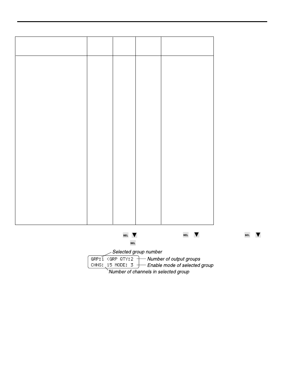
Screen
MAIN SCREEN
to CONFIG MENU
to INITIAL SETUP
to
OUTPUT GROUPS
Begin by moving the cursor to GRP QTY and entering the number of groups desired,
followed by ENT (or use the INC/DEC keys).
Next, move the cursor to GRP and enter “0” followed by ENT.
Move the cursor to CHNS and enter the number of output channels to be included in
Group 0, followed by ENT (or use the INC/DEC keys).
Move the cursor to MODE and enter the operating mode for the group from zero to five,
followed by ENT (or use the INC/DEC keys). See Section 6 for an explanation of the
operating characteristics of each mode.
Move the cursor back to GRP and repeat these steps for each group to be programmed.
When output channels are divided into groups, the appearance of the Main Screen will
change slightly. See MAIN SCREEN for details.
(continued)