Pl-1746 section 4-1 pls functions, Analog output, 1 pls functions – Electro Cam PL-1746 Series User Manual
Page 46
4-1 PLS Functions
Analog Output
Backplane
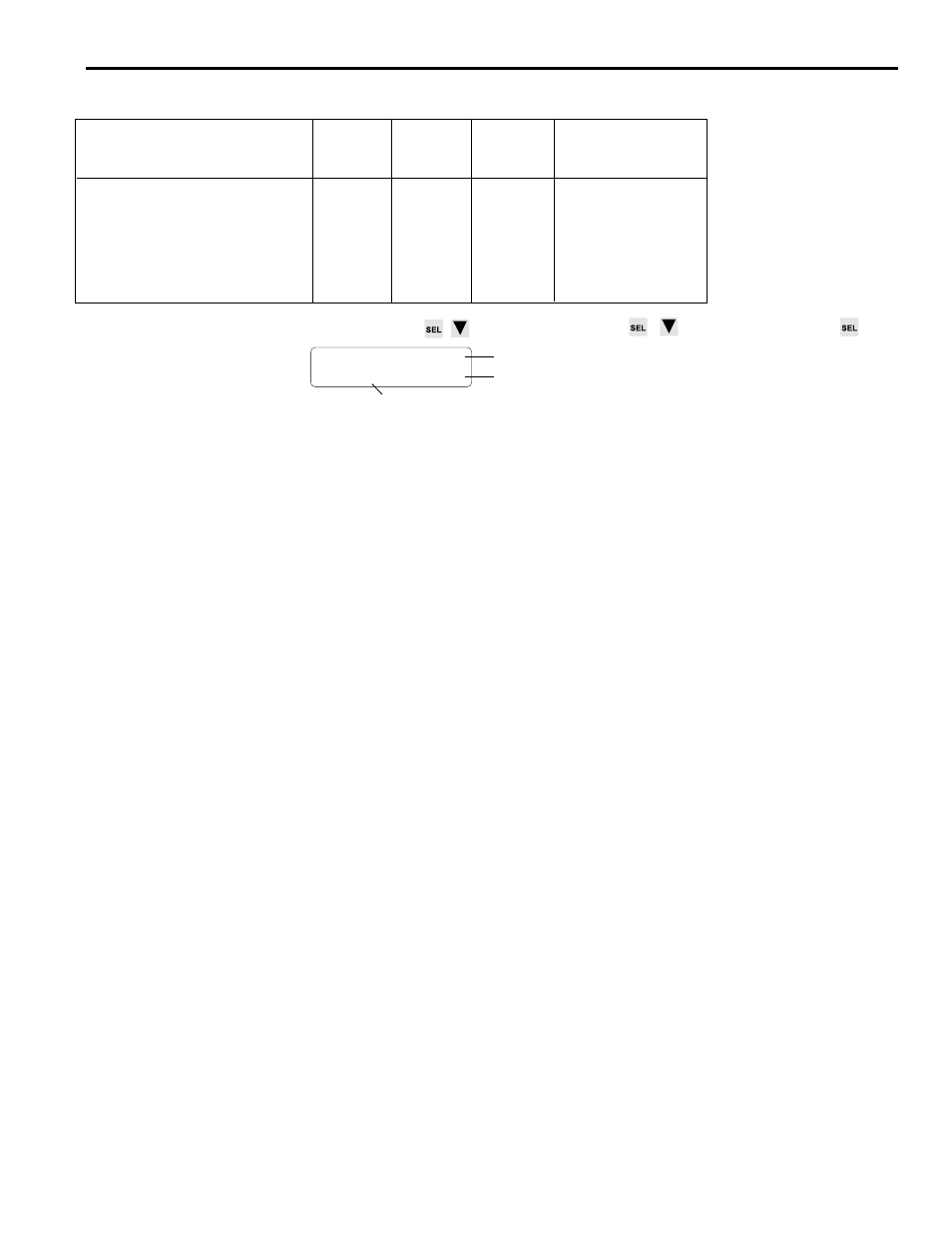
PL-1746 Function Name
SLC 500
Mapping Read/
Valid Range for Data
File
Index
Write
Address
Number
Capability
Analog Output 1 Offset
M0:S.41
210
R/W
0-4095
Analog Output 1 High RPM
M0:S.42
212
R/W
0-3000
Analog Output 1 Value
M0:S.43
214
R/O
0-4095
Analog Output 2 Offset
M0:S.44
216
R/W
0-4095
Analog Output 2 High RPM
M0:S.45
218
R/W
0-3000
Analog Output 2 Value
M0:S.46
220
R/O
0-4095
Screen
MAIN SCREEN
to FUNCTION MENU
to ANALOG OUTPUT
ANALOG OUTPUT: 1<
OF: 20 HI: 1500
Analog Output Number
Analog Output High RPM
Analog Output Offset
To enter an Analog Output number, move the cursor to “Module” and use the numeric
keys and ENT.
To program High RPM, move the cursor to “HI” and use the numeric keys and ENT.
To program Analog Output Offset, move the cursor to “OF” and use the numeric keys
and ENT.
Description
Analog output signals are linearly proportional to resolver RPM. Two types of analog
output modules are available: 0-10 VDC and 4-20 mA.
This function assigns Offset and High RPM values to analog outputs.
• Characteristics can be programmed for Analog Outputs #1 and #2 even if no analog
modules are physically installed in the PS-4108 rack.
• Before programming Offset and High RPM for Module #2, be sure the Analog Quan-
tity function is set to 2. Otherwise, programming for Analog Output #2 will not be
available.
High RPM
Analog High RPM is the resolver speed at which full scale analog output will occur. It is
programmed in whole RPM. When this speed is reached, the analog output signal level
will be at full scale (10 VDC or 20 mA). Increasing speed beyond the High RPM will not
increase the analog output beyond full scale.
Offset
Analog Offset is the analog signal level that will be output when the resolver is at zero
RPM. This allows the minimum analog signal to be greater than 0V or 4 mA. Because
the analog output has 4096 increments (12 bits) of signal level available, the offset is
specified as the number of increments of signal that should be output at zero RPM.
Calculate Analog Output Offset values as follows:
For 0-10 VDC: (Minimum Signal/10) x 4096
Example: For a 2 VDC minimum signal; Offset = (2/10) x 4096 = 819
For 4-20 mA: ((Minimum Signal - 4)/16) x 4096
Example: For a 5 mA minimum signal; Offset = ((5-4)/16) x 4096 = 256