Electro Cam PL-1746 Series User Manual
Page 120
8-7 Utility & Example Ladder Programs
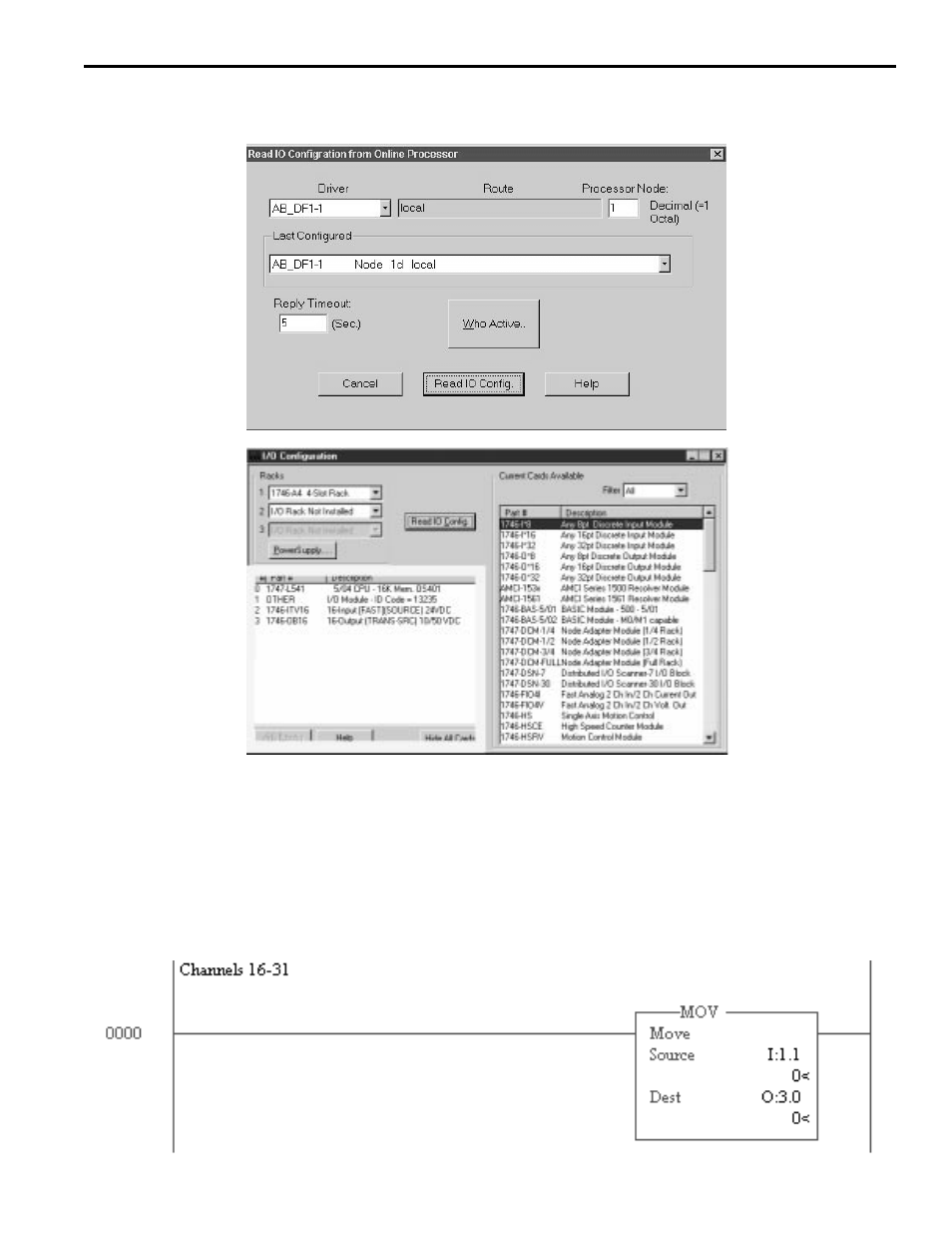
Once the I/O Configuration of your rack is read, the cards which are installed in the rack you are working with will be listed
as in the highlighted box shown in figure 4. In this example, slot 1 contains the PL-1746, slot 2 contains an A-B 16 input
card, and slot 3 contains an A-B 16 output card. As you may already know, the SLC CPU must reside in Slot 0.
Depending on the type of CPU, input/output and A-B rack size, your setup might not look the same. Yours will probably
be different than the example shown above. The only requirement for the PL-1746 to operate is that your CPU is 5/03 or
higher. Neither input nor output cards are necessary for this program to run in your system. The only exception to this
is if you would like to have the output channels from the PL-1746 present in one of your output channels. If no output
module is present in your rack, then Rung 0000 will need to be deleted in order for this program to run prorperly. Click on
rung 0000 once, then push the delete button.
Once the ‘I/O Configuration’ has been pushed, the window shown in figure 3 will open. In order to read what the I/O
Configuration is in your unit, the ‘Read IO Config’ button shown in Figure 3 must be clicked once.
Figure 3
Figure 4
C01 & C04 Example.rss (cont’d)