14 installation – Electro Cam PL-1746 Series User Manual
Page 24
2-14 Installation
Overview
The PS-4108-13-L08 I/O rack provides inputs, analog outputs, and digital power outputs (requiring Slimline™ solid state
relays) for the PL-1746 programmable limit switch plug-in modules. The rack is UL/C-UL listed. CE marking is pending.
PS
The rack is a member of Electro Cam Corp.’s PL
µ
S product line.
41
The rack is mounted external to the Allen-Bradley module chassis.
08
The rack has 8 inputs.
13
The rack and PLS module communicate via Electro Cam Corp.’s proprietary
Type 13 communications.
L
The rack has two SLIMLINE analog output module slots.
08
The rack has 8 SLIMLINE solid state slots.
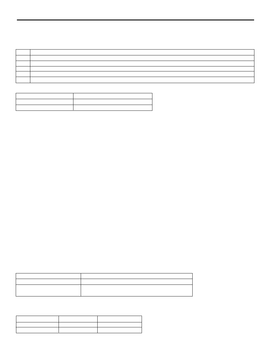
Environmental Requirements
Operating Temperature
0 to 55
°
C (32 to 131
°
F)
Storage Temperature
-40 to 70
°
C (-40 to 160
°
F)
Humidity
95% maximum, non-condensing
For indoor use only.
For use at altitudes up to 2000 m (meters).
Overvoltage Category I. Pollution Degree I.
CE Installations
For installations that must comply with CE requirements the PL-1746 and PS-4108 must be mounted inside a metal
enclosure. In addition, a CoreCom 20VK6 or equivalent single stage PI filter must be connected across the AC input to
the SLC power supply. A Steward 28A2025-0A0 or equivalent ferrite bead must be snapped onto the resolver cable as
close to the enclosure wall (inside) as possible.
Installations must comply with all other manufacturer's requirements.
Mounting & Grounding
The rack’s mounting channel is held to either EN 50035 G profile or EN 50035 top hat profile DIN rail via three mounting
clips. The rack has a 4-40 captive nut connected to the ground plane that must be tied to earth ground in the customer’s
installation. This must be done to maintain EMC compatibility.
Cabling
The primary communications connector (see the connections drawing) on the rack is connected to the PLS module via
the special rack cable. The secondary communications connector allows the user to daisy-chain a second rack to the
first. These connections provide both for receiving input power from the PLS and for communication with the PLS. The
aggregate length of all rack cables attached to a given PLS module must be 50 feet or less. The cable’s shield is tied to
the metal jacket covering the connectors on both ends. The jackscrews of the second DB9 are tied to ground on the
PCB, while those of the first DB9 are not. Thus the shield of each cable is tied to ground at only one end.
Power
The input voltage delivered to the PS-4108 rack from the PL-1746 PLS module is nominally 24V (20V min, 30V max)
at a maximum of 250mA.
Fusing
Power Input Fuse (F1)
1/4 A, 250 V, TR5-F (European Style)
Spare Output Module Fuse(F3) 4 A, 250 V, TR5-F (European Style)
Fuse Tester
The rack includes a green LED (D3) that lights when
a good fuse is installed in the fuse tester.
Communications
DIP switch S1 selects the rack’s physical address. Note that if only one rack is used it must be addressed as rack 0.
Physical Address
Switch 1 (A0)
Switch 2 (A1)
0
ON
ON
1
OFF
ON
Rack Addressing
PS-4108-13-L08 I/O Rack Installation