15 installation – Electro Cam PL-1746 Series User Manual
Page 25
2-15 Installation
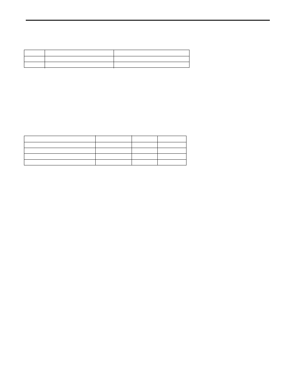
Termination resistors for the data and clock differential pairs are switched into the communications circuit by the S1 DIP
switch. Line termination should be employed only on the rack furthest from the PLS module.
Switch
OFF
ON
3
Data Line Not Terminated
Data Line Terminated into 120W
4
Clock Line Not Terminated
Clock Line Terminated into 120W
Line Termination
Inputs
The rack has 8 inputs, and up to two racks can be daisy-chained in a given system; however, the inputs for the second
rack are ignored. Each input is optically isolated and has a green LED status indicator. The terminals are labeled I0
through I7. All user connections to the inputs are made via a pluggable header. Each input has a single terminal and
there is one common terminal, labeled C. An input’s state is a logic one when current is flowing through its terminal on
the connector, and it’s state is a logic zero when current is not flowing. The inputs are not fused.
•
To source current to the inputs, wire the rack’s common terminal to the negative terminal of an
external power supply.
•
To sink current from the inputs, wire the rack’s common terminal to the positive terminal of an
external power supply.
Minimum
Typical
Maximum
Absolute Maximum Voltage
----
----
30 V dc
Pickup Voltage
9.2 V
11.0V
Dropout Voltage
7.0V
9.2V
----
Current Draw
----
3.5mA
20 mA dc
See datasheet for Phoenix 1755804 header and 1792825 plug for insulation ratings.
Digital Outputs
The rack has 8 relay slots, so the maximum of two racks allows a system total of 16 power outputs. Additionally, a PS-
4108-13-L16 can be added to a PS-4108-13-L08, but be aware that real-world outputs 8-15 will be skipped. Digital
outputs are provided by SLIMLINE solid state relays or reed relays, and thus have specifications dependent on the
relays used. All user connections to the outputs are made via pluggable headers, and plugs are included with the rack
when it is shipped from the factory. The output terminals are labeled M0A, M0B through M7A, M7B, where the number
is the output number and dc conventional current flows into the B terminal and out of the A terminal.
The maximum current rating for each module installed in the PS-4108 rack is as stated in the module's specifi-
cations, OR 1.5 amps, whichever is less.
See datasheet for Phoenix 1755794 header and 1792812 plug for insulation ratings.
Analog Outputs
The rack can control up to two
analog modules in positions A0 and A1. Only one rack (the one with address 0) in a given
system can have analog outputs. Analog outputs are provided by slimline analog modules, and thus have specifications
dependent on the modules used. A pluggable header is used for wiring to the analog outputs, and a plug is included with
the rack when it is shipped from the factory. The terminals are labeled such that, for analog output 0, conventional
current flows out of the A0 terminal, through the load, and returns to the - terminal for analog output 0. Similarly, for
analog output 1, conventional current flows out of the A1 terminal, through the load, and returns to the - terminal for
analog output 1.
See datasheet for Phoenix 1755752 header and 1792773 plug for insulation ratings
Status Indicators
RUNNING
During normal operation the green
RUNNING LED (D12) is lit.
COMMUNICATIONS
When Rack-to-PLS communications are ongoing the yellow
COMMUNICATIONS LED (D11) is lit.
PS-4108-13-L08 I/O Rack Installation