Pl-1746 appendix - output pulse programming, Monitoring the error registers & execute busy bit, Programming on/off pulses to the pl-1746 memory – Electro Cam PL-1746 Series User Manual
Page 140: Output pulse programming, Appendix-1 output pulse programming
Appendix-1 Output Pulse Programming
Output Pulse Programming
This section will explain how to program ON/OFF pulses or “dwells” in the PL-1746 card via the SLC 500 backplane M0
files, using a ladder program or a touch screen interface.
Monitoring The Error Registers & Execute Busy Bit
It is recommended that the following error registers be monitored when writing information to the PL-1746.
If a command is written and no result is seen, check these error registers to see what type of error has occurred.
1. Module Status register I:S.7 (Clear errors with bit O:S.0/8).
Note: Errors in this register must be cleared or no
further commands will be accepted.
2. The error bits 10 through 15 in Pulse Edit Command Status register M0:S.902.
3. It is also recommended to monitor the execute/busy bit in the Pulse Edit Command Status register M0:S.902 bit 0.
This bit is required to execute commands,and will stay high until a pulse edit command has been completed.
Writing subsequent commands before this bit goes low will result in errors.
Programming ON/OFF Pulses to the PL-1746 Memory
There are 2 steps in this process as follows:
1. Enter the data to be written in the Pulse Edit M0 files (M0:S.896 – M0:S.901).
2. Enter the proper read or write command in the Command Status register (M0:S.902) to execute the M0 file data.
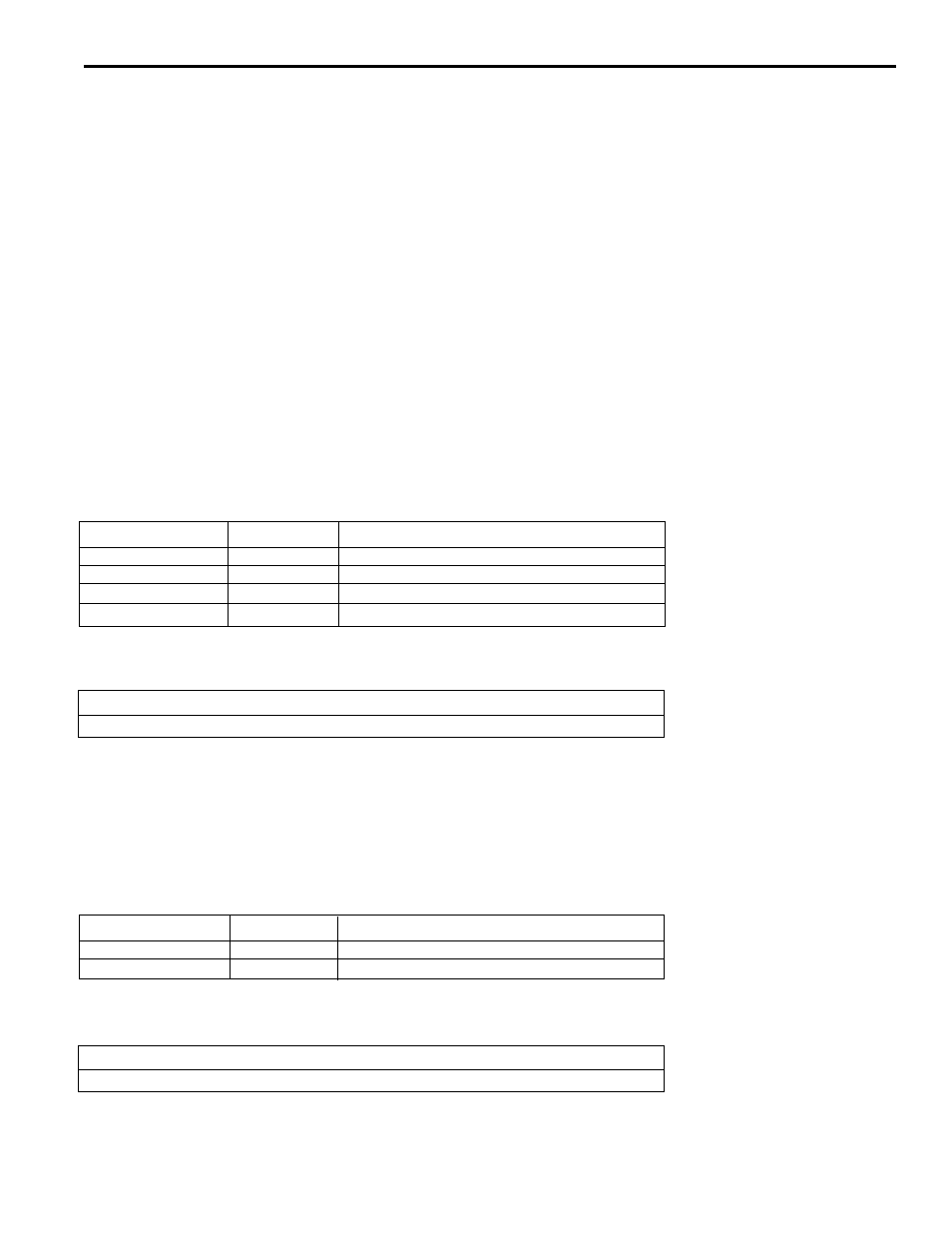
Example 1: Program a pulse in Program 0, Channel 1, of ON = 90, OFF = 180.
1. Since this is a write command, it requires (see table 1) that we enter the program, channel and on/off data in the
M0 files (see table 2).
Data to enter
M0 file
Purpose
0
M0:S.896
Program number
1
M0:S.897
Channel number
90
M0:S.898
On: Start position of pulse
180
M0:S.899
Off: End position of pulse
1. After entering the proper information above, a command is now required in the Command Status register M0:S.902
(see tables 3 & 4).
Command
bit 4
bit 3
bit 2
bit 1
bit 0
(decimal)
Write
0
0
0
1
1
3
Once the command bits are entered, the data in the M0 files will be written to the PL-1746 memory. The execute/busy
bit 0 will stay a “1” until the write is completed when it will return to “0”.
Example 2: Read the ON 90, OFF 180 pulse programmed in Program 0, Channel 1 in Example 1 above.
1. Since this is a Read command, it requires (see table 1) that we enter the program & channel data in the M0 files
(see table 2). Note: If there were more that one pulse in the channel being read, we would also need to specify the
Pulse number. First pulse in channel is considered pulse #0, second pulse #1, etc.
Data to enter
M0 file
Purpose
0
M0:S.896
Program number
1
M0:S.897
Channel number
1. After entering the proper information above, the command for a read is now required in the command status
register M0:S.902 (see tables 3 & 4).
Command
bit 4
bit 3
bit 2
bit 1
bit 0
(decimal)
Read
0
0
0
0
1
1