Clear-Com HLI-FBS User Manual
Page 21
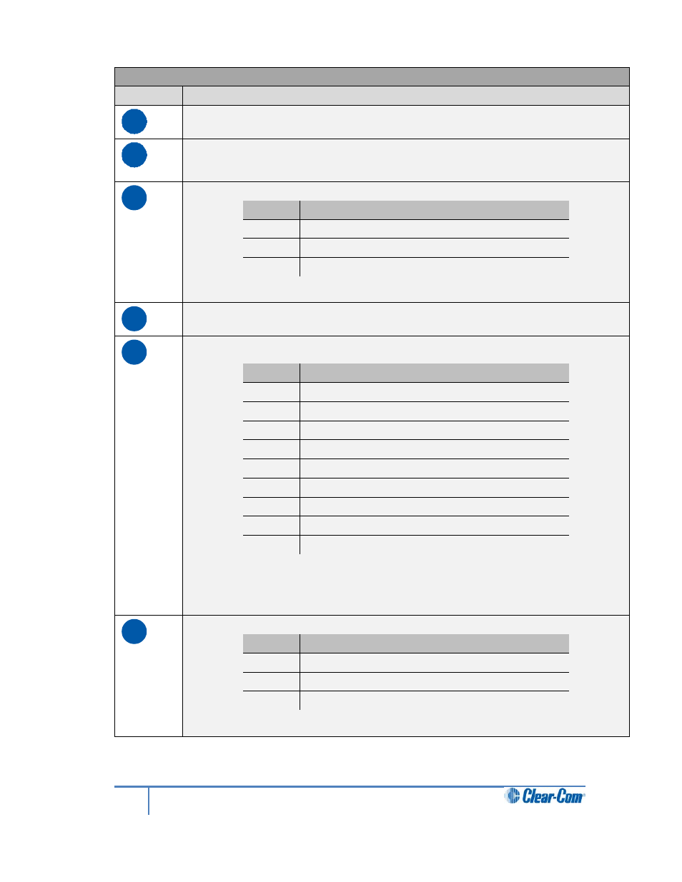
Key to Remote Station: rear panel
Feature
Description
A
PSU holder for a separate external AC-DC power supply. The external PSU
provides the 48V required and at its input takes 100-240V, 50-60Hz.
B
Power supply. The power input connector is a low voltage DC connection. It is
48VDC at a max power of 12.95W
.
C
Line 1 (partyline). (3-pin male and female XLR connectors).
Pin
Function
Pin 1
Ground
Pin 2
+30V DC and Audio
Pin 3
-30V DC and Audio
Table 2-17: Line 1 pin out
D
Power Over Ethernet (RJ45 connector)
E
Control input/output (DB9 connector)
Pin
Function
Pin 1
Audio out +
Pin 2
Audio in +
Pin 3
GND
Pin 4
Relay NC
Pin 5
Relay NO
Pin 6
Audio out -
Pin 7
Audio in -
Pin 8
Opto
Pin 9
Relay pole
Table 2-18 Control input/output pinout
The audio connections in this connector are wired directly to the SA and
program connectors. Only one or the other can be used at one time.
F
SA [Stage Announce] line out (3-pin female XLR).
Pin
Function
Pin 1
Ground
Pin 2
Positive
Pin 3
Negative
Table 2-19 SA pinout
21
HelixNet Partyline User Guide