Clear-Com HLI-FBS User Manual
Page 15
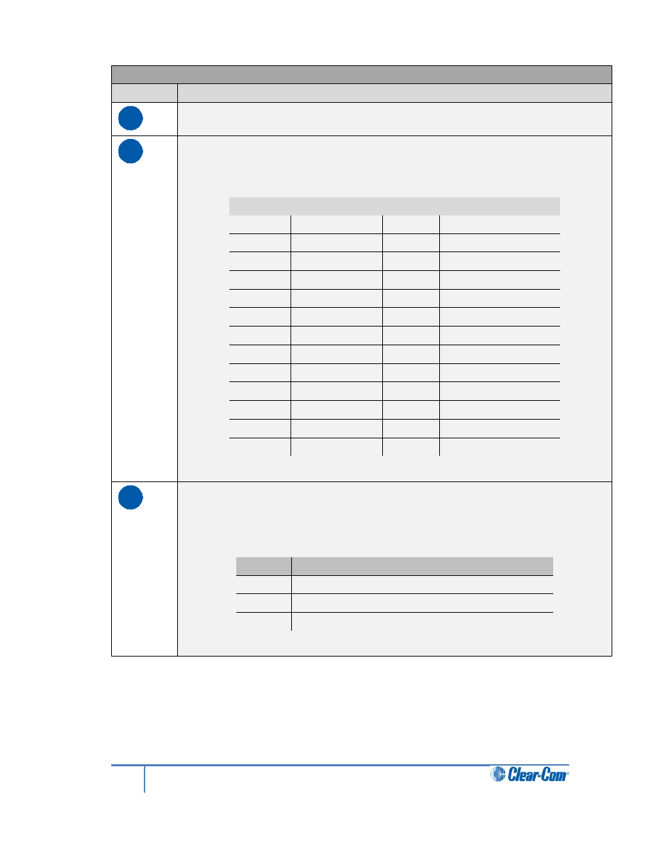
Key to Main Station: rear panel
Feature
Description
A
Power supply with metal cable clip. The power supply operates at 100 - 240
VAC / 50-60Hz /
250 watts / T 3.15A H 250 V.
B
Control I/O (25 way female D-type). Use to connect up to 4 relay control
outputs and 4 optically isolated control inputs (see 4.5 Configuring the Control
I/O).
Pin
Function
Pin
Function
Pin 1
Relay 1 NC
Pin 14
Relay1 Pole
Pin 2
Relay 1-NO
Pin 15
Relay 2 NC
Pin 3
Relay2-Pole
Pin 16
Relay 2-NO
Pin 4
Relay 3 NC
Pin 17
Relay3 Pole
Pin 5
Relay 3-NO
Pin 18
Relay 4 NC
Pin 6
Relay4-Pole
Pin 19
Relay 4-NO
Pin 7
Pin 20
+5V
Pin 8
GND
Pin 21
+5V
Pin 9
GND
Pin 22
Opto 1-
Pin 10
Opto 1+
Pin 23
Opto 2-
Pin 11
Opto 2+
Pin 24
Opto 3-
Pin 12
Opto 3+
Pin 25
Opto 4-
Pin 13
Opto 4+
Table 2-6: Control I/O pin out
C
Hot Mic output. This connection is a 1/4-in (0.64 cm) phone jack. It provides an
output signal from the selected headset or panel microphone. The Hot Mic
output is always live. Audio from the mic is routed through the Hot Mic output
even if the mic is inactive (off).
Pin
Function
Tip
Mic
Ring
IFB mute signal
Sleeve
Ground
Table 2-7: Hot Mic pin out
15
HelixNet Partyline User Guide