Clear-Com HLI-FBS User Manual
Page 16
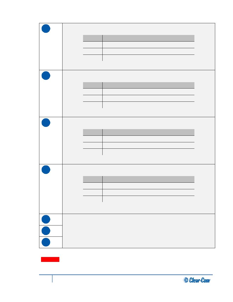
D
SA [Stage Announce] line out (3-pin male XLR).
Pin
Function
Pin 1
Ground
Pin 2
Positive
Pin 3
Negative
Table 2-8: SA pin out
E
Program Input (3-pin female XLR).
Pin
Function
Pin 1
Ground
Pin 2
Positive
Pin 3
Negative
Table 2-9: Program input pin out
F
Line 1 (partyline). (3-pin male and female XLR connectors).
Pin
Function
Pin 1
Ground
Pin 2
+30V DC and Audio
Pin 3
-30V DC and Audio
Table 2-10: Line 1 pin out
G
Line 2 (partyline). (3-pin male and female XLR connectors).
Pin
Function
Pin 1
Ground
Pin 2
+30V DC and Audio
Pin 3
-30V DC and Audio
Table 2-11: Line 2 pin out
H
Slots for optional interface modules. For more information, see HMS-4X Main
Station rear panel: Interface modules.
I
J
Table 2-12: Key to HMS-4X Main Station rear panel diagram
Warning:
Only connect power supply to earthed supply sockets. Ensure that the power
supply is routed to avoid sharp bends, hot surfaces, pinches and abrasion.
For more safety guidance, see the Safety Instructions at the front of this guide.
16
HelixNet Partyline User Guide