Optional axle level lift cylinder repair – Alamo HYDRO 15 User Manual
Page 98
HYDRO 15 (Service Manual) 10/06
© 2006
Alamo Industrial
Section 5 - 24
OPTIONAL AXLE LEVEL LIFT CYLINDER REPAIR
Cylinder Removal: ( Axle Level Lift Cylinders -Optional)
1.
Make Certain
axles and wings are in the lowered position before disconnection any compo-
nent
.
Make certain tractor is securely parked with brakes set
.
Make certain
tractor engine is in off
position and
key secured to prevent starting
. It is recommended mower be disconnected from
tractor and/or battery cable be removed from battery while repairs are being made.
Front and rear
of mower must be securely supported on strong jackstands before hydraulic lines or cylinder
mounting pins of the axle hydraulic assembly are disconnected.
2.
Make certain
that all hydraulic pressure has been released from lines after wings and axles
have been completely lowered. This may require the tractor hydraulic controls and / or remote
control valve be worked to release hydraulic pressure.
NEVER disconnect any cylinder hydraulic
hose's or fittings if all
mower components (wings and deck) are not resting in the completely
lowered to the ground position or supported on jackstand position.
3.
Do not remove cylinder pressure hose before the cylinder is dismounted from deck. Remove
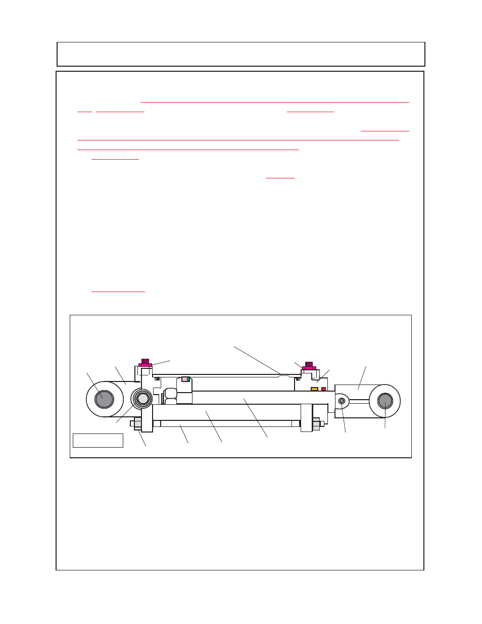
the cylinder mounting pins
(figure 1 item 1)
, this allows the cylinder to be raised upward off the deck
mounting lug and the axle lug. Place a drain pan under the pressure hose to catch the hydraulic
oil when hose is disconnected. Drain cylinder and hose into drain pan. Plug the pressure hose and
cylinder to keep contamination out of them.
4.
Plug all openings in cylinder before cleaning the cylinder. Base end of cylinder
(figure 1 item
8)
will have two ports, Pressure in hose port
(figure 1 item 11)
and second plugged port on side
(figure 1 item 12)
which should still be in the cylinder base. The other port on the cylinder head is
the bypass pressure out port.
5.
IMPORTANT!
These cylinders must be marked so the barrels will be rassembled with the
bypass grooves in the rod end, or the repair technician must keep in mind that the barrel end with
the groove machined into the ID must always be assembled with groove to the rod end.
Cylinder Dis-Assembly: (Axle Level Lift Cylinders Optional)
1.
This is a Tie-Rod construction type cylinder, the four tie-rods
(figure 1 item 6)
and the 8 hex
nuts
(figure 1 item 7)
bolt the cylinder together. When these tie-rods are unbolted the cylinder will
come apart with minimum effort but
DO NOT
unbolt tie-rods until later.
It is a must
that the barrel
of the cylinder be marked as to which end is the cylinder rod end and which is the cylinder base
clevis end and the barrel reassembled on the same end as removed.
2.
Place the cylinder in a bench vise
(figure 2)
, use pieces of wood or other soft material between
vise jaws and cylinder barrel.
DO NOT
over tighten vise and distort the shape of the barrel, vise
only needs to be tightened enough to hold cylinder.
12345678
12345678
12345678
12345678
12345678
12345678
12345678
1234
1234
1234
1234
1234
1234
12345678
12345678
12345678
12345678
12345678
12345678
12345678
12345678
12345678
12345678
12345678
12345678
12345678
12345678
12345678
12
12
12
1234567890123
1234567890123
1234567890123
1234567890123
1234567890123
12345678901234567890123456789012123456789012345678
12345678901234567890123456789012123456789012345678
12345678
12345678
12345678
12345678
12345678
123
123
123
1
1
1
1
1
1234567
1234567
1234567
1234567
1234567
1234567
1234567
123
123
123
12
12
Figure 1
1
1
2
3
4
6
5
7
9
8
10
11
12
Pressure bypass Groove in ID of Barrel at the
cylinder head end.