Speed increaser service & repair, Figure 5 – Alamo HYDRO 15 User Manual
Page 119
Section 7 - 9
HYDRO 15 (Service Manual) 09/06
© 2006
Alamo Industrial
Speed Increaser Service & Repair
5.
To split the housing halves remove the 8 bolts, lockwashers and nuts
(figure 4 item 31, 32 & 33)
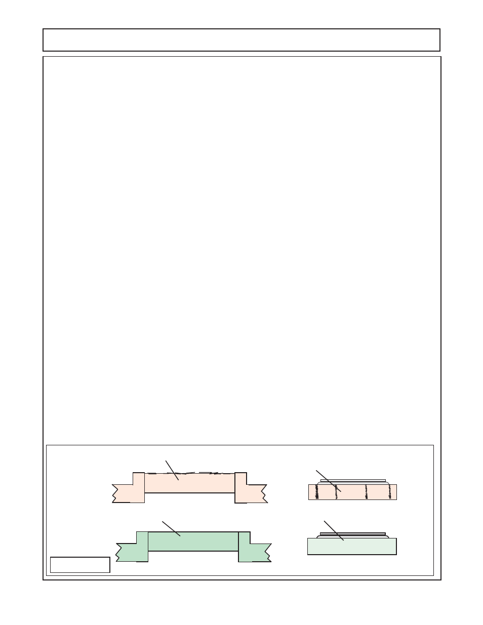
. This
will allow the two housing halves
(figure 4 item 15 & 16)
to be separated. If it is necessary to pry the housing
halves apart use extreme caution not to damage the machined surface of the housing halves. Pry in
alternating areas so the halves are separated as evenly around as possible. There are two dowel pins
(figure
4 item 17)
used to align the housing halves, this usually where the housing are the most difficult to pull apart.
6.
With the gears and shafts
(figure 4 item 2 & 5)
exposed pull them up and out of the housing half
(figure
4 item 15 & 16)
. The bearing cones
(figure 4 item 14 & 20)
should stay on the gear shafts, the bearing cups
(figure
4 item 13 & 19)
should stay in the housing halves. The bearing cups will be rather simple to remove
from the pump side housing half, remove any snap rings
(figure 4 items 35)
and the bearing cups can be
pressed out. Make certain to support the housing half while pressing out bearing cup.
7.
Turn the PTO housing halve over to remove the closed cover
(Figure 4 item 7)
and the open cover
(figure
4 item 9)
from the PTO side housing half
(figure 4 item 15)
. Remove the closed cover and the open cover by
removing the 6 bolts and lockwasher that retain them. Make a note as the amount of shims that are installed
behind closed cover and open cover, this will give fair indication of what is need during re-assembly. Remove
bearing spacer
(figure 4 item 11 & 35)
and press bearing cups out of housing half. Remove the seal
(figure 4
item 10)
from the open cover
(figure 4 item 9).
8.
Remove bearing cones
(figure 4 items 14 & 20)
from gear shafts
(figure 4 items 2 & 5)
, the removal of the
bearing cones will require a bearing puller. When removing the bearing cones from the gear shafts use caution
not to damage the bearing cone or the shaft surface.
9.
Inspect and clean all components that have been dis-assembled from speed increaser. Inspect the seals
that were removed. Clean both housing halves. Inspect all machine surfaces of housing for scratches and
damage. Wash all parts, clean old gaskets off and air dry
(DO NOT SPIN DRY BEARING CONES WITH
COMPRESSED AIR, this will damage bearing cones).
10.
Inspect old seals and seal openings
(Figure 5)
for damage to old seals that may have been caused by
covers and or plates. One of the most common problems is damaged sone when the original seal or when a
replacement was installed previously. When installing seal there are a number of ways the damage can
occur, hitting opening with seal driver, hitting opening with hammer or hitting opening when removing old seal.
The top opening is not chamfered and the metal will mash down and lay over the side, this can usually be
identified by scratches that run across the OD of the seal as shown in
figure 5
. This can be and should be
fixed by using emery cloth and carefully removing these burrs on the outer edge, only the burrs on the outer
edge should be removed, not material inside the ID of the opening.
11.
Inspect bearings, cups and cones, housing halves, gears and shafts, covers, bolts, nuts and washers.
Replace any components that are not serviceable. DO NOT mix old worn parts with new parts, the worn parts
will decrease the life of the repair parts.
Damaged (burrs) Seal opening in
cover
Good Seal opening in cover
Seal Removed from Damaged
(burrs) opening in cover
Seal Removed form good opening
in cover
FIGURE 5