Pump service & repair, Figure 38 figure 40 – Alamo HYDRO 15 User Manual
Page 36
HYDRO 15 (Service Manual) 09/06
© 2006
Alamo Industrial
Section 2 - 20
PUMP SERVICE & REPAIR
17.
Lightly coat the gear journals with grease. When placing the
Bearing housing
(figure 10 item 13)
over gears,
use caution
so you
don't hit and damage gear shaft journals. Place the bearing carrier
onto gear shaft journals of the drive and the driven gears.
Be sure
to align the dowel pin holes
over with dowel pins. When the parts are
parallel squeeze them together or alternately tap over each dowel
until the parts are together.
DO NOT
use excessive force to put
housing together, if light taping won't do it something is wrong
(figure
42).
18
Insert the 4 studs, 4 Lockwashers & 4 Nuts
(See figure 23A)
that
connect the previous sections. Tighten the stud nuts in alternating
pattern until Torque of the nuts to 3000 in. lbs. (250 ft. lbs.)
19.
Coat the connecting shaft
(figure 10 item 14)
use light coat of
grease, insert it into spline of drive gear. Make certain that gasket
seals are coated with clean grease and installed into second gear
housing as instructed in
step 12.
Position and place second gear
housing
(figure 10 item 16)
making certain the dowel pins are kept
aligned between two castings
(figure 43 & 44)
. Housing should fit
flush to bearing housing.
MAKING CERTAIN
the marks made to
keep the components in the same orientation when re-assembled
are aligned
(figure 23A)
.
20
Place the thrust plate
(figure 10 item 7 & 8)
into the gear housing
as
per step 14.
Coat the
journal of the drive gear
and the driven gear insert
with light coat of grease.
Figure 39
Figure 37
Figure 41
Figure 42
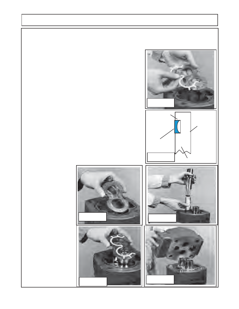
Gear Side
Smooth
Channel Seal
Side Grooved
Smooth Side
Channel Seal
Outward
123456
123456
123456
123456
123456
123456
123456
123456
123456
123456
123456
123456
123456
123456
123456
123456
123456
123456
123456
123456
123456
1234
1234
1234
1234
1234
1234
1234
1234
1234
1234
1234
1234
1234
1234
1234
1234
1234
1234
1234
1234
1234
1234
1234
1234
1234
1234
1234
1234
1234
1234
1234
1234
Thrust Plate
Figure 38
Figure 40
16.
Slip the next thrust plate with the channel seal installed
(figure 10 item 7 & 8)
over the gear journals and into
the housing bore. The flat side of the seal should face up with the relief groove of thrust plate facing the outlet
side. Check the gear housing gasket seal
(figure 10 item 10)
is still in place on gear housing
(figure 24 & 41).
the drive gear aligning the
splined shaft end over the
splined connecting shaft.
Insert the driven gear into
the gear housing aligning
gear teeth with the drive
gear.
DO NOT
force the
gears in, they must slide
in smoothly and mesh
together
(figure 44)
. Make
certain the gears are
seated completely down
and against the thrust plate
face.