Leveling control rods service & repair, Leveling control rods - assembly & adjusting, Figure 6 figure 7 – Alamo HYDRO 15 User Manual
Page 140
HYDRO 15 (Service Manual) 09/06
© 2006
Alamo Industrial
Section 10 - 4
Leveling Control Rods Service & Repair
Leveling Control Rods - Assembly & Adjusting:
Using the drawing in figure 4 locate and identify the control rod components.
The control
rods will require the proper assembly order in order to be assembled to the mower. The following step are to be used
if the control rods need to be assembled to mower, the reverse of this procedure will be used to dis-assemble the
control rod(s) of the mower.
DO NOT REMOVE OR INSTALL ANY CONTROL ROD COMPONENTS
unless you
first support the mower on Jack Stands in the front and rear.
When replacing any parts the new parts must be
compared to the old existing part for comparison and should be the same.
(MOWER & TRACTOR MUST BE ON
LEVEL AREA
(concrete or pavement preferred) BEFORE LEVELING CAN BE DONE!
1.
From the front side of the center section deck slide eye end of the control rod
(item 1)
into the hole of the
channel on the deck, the threaded end will be to the front.
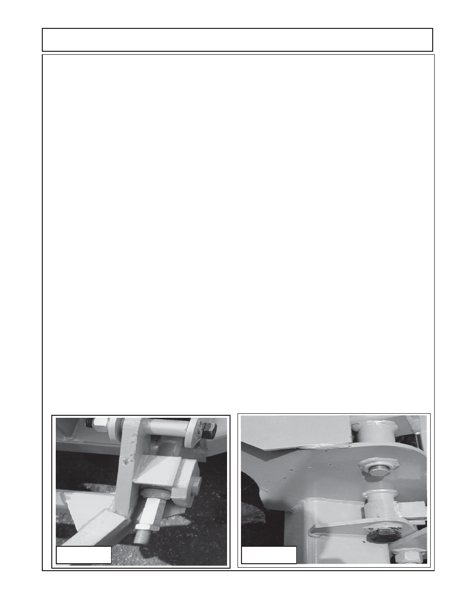
2.
Install the swivel bar
(figure 4 item 2)
into the tongue, if dual control rods there is one on the LH side also
that should be installed now
(figure 6).
3.
From the back side slide the control rod
(item 1)
forwar toward tonge and into the hole of the swivel bar
(item 2),
this will mot likely require two people
. The hole in the swivel block will be larger than the control rod
diameter
(figure 4 & 6).
4
Select the correct bushing weldment
(item 3 should be same as existing part)
, slide the bushing
weldment
(item 3)
over the threaded end of the control rod
(item 1)
and through the hole of the swivel bar
(item 2)
until the shoulder in bushing weldment is against the swivel bar
(figure 4, 5 & 6)
5.
Start the adjusting nut
(item 4)
on to the threads of the control rod
(item 1),
only start the threads do not
screw the adjusting nut on completely. Push the control rod back toward the rear of the mower.
6.
Install the rear control rod anchor bolt
(item 5)
by aligning the eye on the control rod with the hole in the
rear axle
(item 9)
. install the locknut
(item 6)
onto the anchor bolt. Tighten the nut untill the slack is out and
the bolt will not slide in or out.
DO NOT
over tighten the bolt and deform the plates on the axle or tighten bolts
so tight the control rod is pinched between the plates of the axle
(figure 7).
7.
Tighten the adjusting nut
(item 4)
until the slack is out of the control rod and the previous components
are seated against each other as explained in previous steps
(figure 4 & 6).
The LH and RH control rods
(on
dual control rods)
should be assembled as explained above.
Figure 6
Figure 7