Standard axle lift cylinder repair – Alamo HYDRO 15 User Manual
Page 94
HYDRO 15 (Service Manual) 10/06
© 2006
Alamo Industrial
Section 5 - 20
STANDARD AXLE LIFT CYLINDER REPAIR
4.
Install the new Piston retaining locknut
(figure 6 & 7 item 14)
onto the cylinder rod. (Note it is
not recommended that old locknut be reused). Before tightening the locknut down make certain
that piston is seated onto cylinder rod completely, this can be done by visually inspecting back side
of piston against shoulder of cylinder rod. Torque Piston Locknut
300 ft lbs
(based on 1” locknut).
When tightening piston locknut if support for cylinder rod is needed
(see figure 4)
.
5.
Install the new nylon thread protector
(figure 6 item 2)
into the cylinder rod clevis
(figure 6 item
3)
, Make certain the nylon thread protector is laying flat in the bottom of the threaded hole in the
clevis. Insert the setscrew
(figure 6 item 2)
into the clevis
(figure 6 item 3)
. Tighten the clevis
setscrew to
20 ft. lbs.
6.
Clamp the barrel
(figure 8 item 5
) in vise using wood or other soft material to protect barrel
(see
figure 8)
,
DO NOT
tighten vise so tight that the barrel becomes distorted. Make note that the mark
that was made to identify which end of the barrel was the rod end is verified. Coat the inside of the
barrel with hydraulic oil.
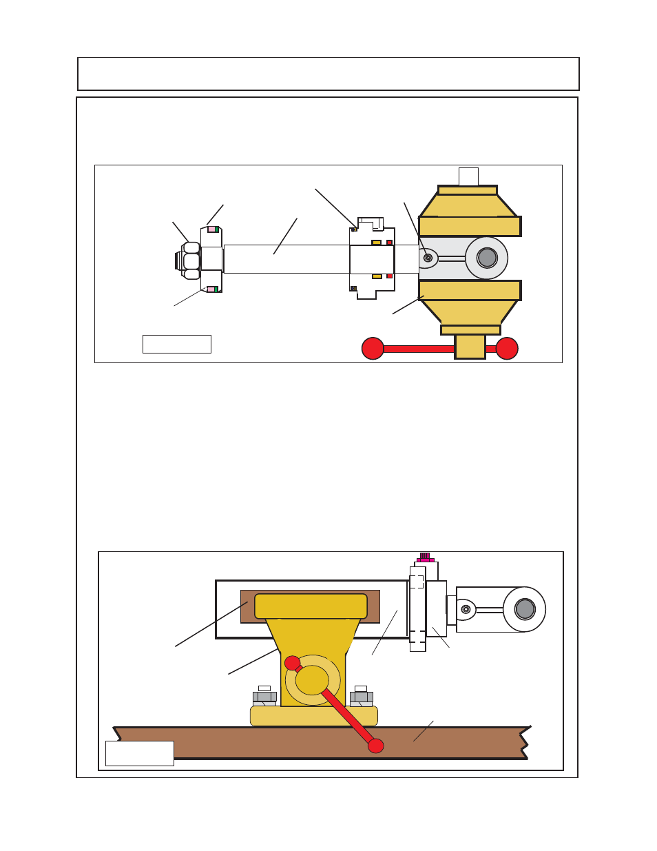
7
Coat the piston, cylinder rod, cylinder head seals with hydraulic oil. Holding the rod, clevis,
cylinder head and piston as an assembly.
(see figure 7)
slide the assembly into the barrel. Make
certain that the insertion is on the same end as when it was removed
(Not required only
recommended).
Make certain the port of the cylinder head
(figure 8 item 9)
is pointing up as shown
this will make certain of port alignment when base end of cylinder is installed.
Figure 7
12345
12345
12345
12345
12345
Bench Vise
Cylinder Head
Clevis Set Screw
Piston
Cylinder Rod
12345678901234
12345678901234
12345678901234
12345678901234
12345678901234
12345678901234
12345678901234
12345678901234
12345678901234
12345678901234
12345678901234
12345678901234
12345678901234
12345678901234
12345678901234
12345678901234
12345678901234
12345678901234
12345678
12345678
12345678
12345678
12345678
12345678
123456
123456
123456
123456
123456
123456
12345
12345
12345
12345
12345
12345
Piston Nut
1234567
1234567
1234567
1234567
1234567
1234567
1234567
1234567
1234567
1234567
1234567
1234567
1234567
1234567
1234567
1234567
1234567
1234567
1234567
123
123
12
12
123
123
123
Chamfered side of piston
1234
1234
1234
123
123
Wood or other soft material
Bench Vise
Work Bench
9
(cyl head, clevis, cyl
rod & piston asy).
5
Figure 8