Speed increaser service & repair, Figure 6, Figure 7 – Alamo HYDRO 15 User Manual
Page 120
HYDRO 15 (Service Manual) 09/06
© 2006
Alamo Industrial
Section 7 - 10
Speed Increaser Service & Repair
Re-Assembly for Replacement of Components!
IMPORTANT! Make certain all components have been cleaned, inspected and replaced as required. All
parts must be dry of any cleaning agents. All covers should be cleaned of oil and/or grease.
1.
Make certain the covers
(figure 4 items 6, 7 & 9)
are completely cleaned around the gasket / shim area.
Make certain the mounting surface is flat and undamaged. This is important to assure the covers seal when
installed later.
2.
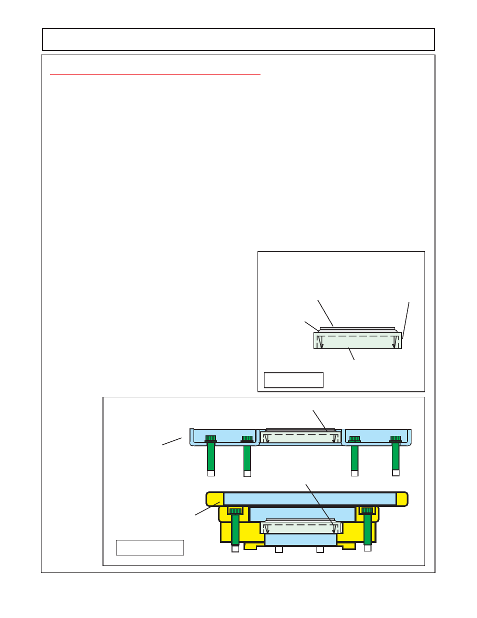
Install seals into covers, there are three seals
(figure 4 item 10)
, these seal are all the same and can be
install in either of the two open covers
(figure 4 item 9)
or in the pump mount flange
(figure 4 item 6)
. The
seals will install
(figure 6)
with the flat side outward. The hollowed side will install inward toward the gears.
Coat the ID of the seal with clean light coat of grease. Coat the OD
(side figure 6)
of seal with Locktite ™ 801
sealer or equal, this will help keep seal from leaking
(figure 6)
. Use the proper dia seal driver to install the
seal. Set the covers with the seals installed aside for now.
3.
Install Bearing Flange Mount
(figure 7)
with new seal already installed to the housing half with the Allen
head
5/16" -NC X 3-1/4" Gr. 5
bolts & lockwasher
(figure 4 item 29 & 30)
There are total of 24 of these bolts
used on speed increaser, they are the same size and length bolts. Make certain the housing half, the one
open cover and the pump mount flange are clean and
FIGURE 6
Flat side
Outward
This Side Inward
Toward Gears
Coat out side dia
of Seal w/Locktite™
801 or Equal Sealer
Coat ID of seal with
light coat of
Clean Grease
free of the old gasket. Install new gaskets
(figure 4
item 24)
to the covers, use light gasket sealer when
installing the covers. Only the one open cover and the
pump cover flange can be installed and torqued to the
housinf half
(figure 4 item 16)
at this time
(figure 9).
Coat the bolt threads with a thread light sealer The 5/
16" bolts will
torque 12 to 15 ft.
lbs. These are to be
torqued in a criss cross pattern
(figure 8).
Do this in
increments to keep the flange and cover m mounted
square and prevent warpage. The pump mount flange
and the open cover mount and toque the same
12 to 15
ft. lbs.
After tightening the open cove and the pump
mount flange make certain the ID of the seals are
coated with light coat of grease.
1234
1234
1234
1234
123
123
123
123
123
123
123
123
123
123
Pump Mount Flange
Open Cover
(Qty 2)
123
123
123
123
123
123
123
123
123
123
123
123
Seal Install From Top
Seal Install From Top
FIGURE 7