Motor service & repair, Figure 42 figure 43, Figure 44 – Alamo HYDRO 15 User Manual
Page 60
HYDRO 15 (Service Manual) 09/06
© 2006
Alamo Industrial
Section 3 - 22
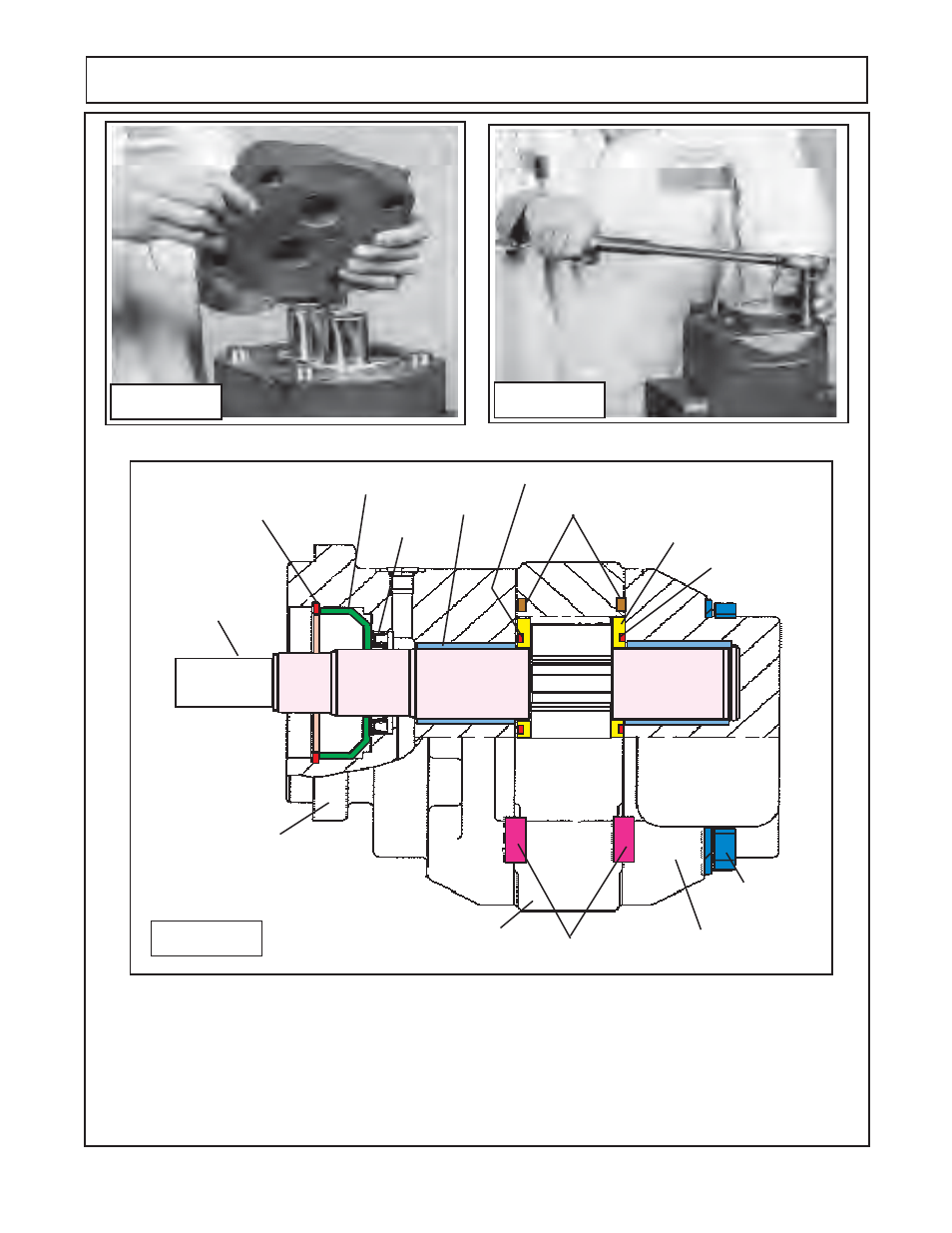
MOTOR SERVICE & REPAIR
Figure 42
Figure 43
12345678901234567
12345678901234567
12345678901234567
12345678901234567
12345678901234567
12345678901234567
12345678901234567
12345678901234567
12345678901234567
12345678901234567
12345678901
12345678901
12345678901
12345678901
12345678901
12345678901
12345678901
12345678901
12345678901
12345678901
12345678901
12345678901
12345678901
12345678901
12345678901
12345678901
12345678901
12345678901
12345678901
12345678901
12345678901
Shaft &
Gear Set
(Drive gear
& Driven
Gear)
Snap Ring
Seal Retainer Cup
Input Seal
Bushing (2)
Channel Seal (2)
SquareHousing Seal
Channel Seal
(2)
Thrust Plate (2)
Shaft End Cover
Dowel Pins (4)
Retaining Bolt &
Washers (4)
Port End Cover
Gear Housing
Figure 44
18
Review all assembly steps to make certain the assembly is correct. Wipe and clean any grease that
may be on the outside of motors. Review the illustration to determine the motors were assembled cor-
rectly. Fill motors with clean oil through the pressure ports, this will assist motor during first start up. IF
PUMP was replaced see start up procedure in pump repair section. If only the motor is being replaced
make certain not to start system if oil is warm and motor is cold. If motor is cold and oil is warm start and
stop system until motor and oil is temperature is equaled. Warm oil and cold motor could damage motor.