Optional axle level lift cylinder repair – Alamo HYDRO 15 User Manual
Page 101
Section 5 - 27
HYDRO 15 (Service Manual) 10/06
© 2006
Alamo Industrial
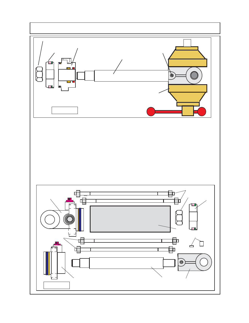
OPTIONAL AXLE LEVEL LIFT CYLINDER REPAIR
2.
After components have been cleaned and inspected, replace any damaged parts. The Piston
Locknut
(figure 6 item 14)
is recommended that it be replaced with new locknut of same rating.
Make a note of which way the seals are installed and in what order. Remove all old seals and
replace them with new ones
(see figure 6),
The nylon thread protector will need to be removed
from the rod clevis and replaced
(figure 6 item 2).
3.
After the seals have been removed inspect all of the grooves where seal seat for condition,
make certain none are bent or distorted, they should not have any damage or wear severe enough
to damage seals. Check for wear, the ID of the barrel
(figure 6 item 5)
, OD of the piston
(figure
6 item 15)
, ID of the cylinder head
(figure 6 item 9)
.
4.
Make certain to inspect the ID of the cylinder barrel, the will be a groove machend into the rod end
of the barrel that will allow the hydraulic oil to bypass from the 1 st cyl to the 2nd cyl and onto the
3 rd cyl, the rod end of the 3 rd cylinder has a goove machined into the rod end which allows the
hydraulic oil to bypass and return thr hydraulic resrvoir of the tractor.
Figure 6
6 & 7
3
4
5
9
8
15
14
1234567
1234567
1234567
12345678
12345678
12345678
12
12
12
12
12
1234567
1234567
1234567
1234567
1234567
1234567
1234567
1234567
1234567
1234567
1234567
1234567
1234567
1234567
1234567
1234567
1234567
1234567
1234567
1234567
1234567
123
123
123
123
123
123
12345
12345
12345
12345
12345
12345
12345678
12345678
12345678
12345678
12345678
12345678
12345678
12345678
12345678
12345678
12345678
12345678
12
12
12
12
12
12
1234567
1234567
1234567
1234567
1234567
1234567
123
123
123
12
12
12
1234567
1234567
1234567
12345678
12345678
12345678
12
12
12
12
12
12
1234
1234
1234
1234
2
6 & 7
Figure 5
123456
123456
123456
123456
123456
123456
Bench Vise
Cylinder Head
Clevis Set Screw
123456
123456
123456
123456
123456
123456
Piston
Piston Nut
12345678901234
12345678901234
12345678901234
12345678901234
12345678901234
12345678901234
12345678901234
12345678901234
12345678901234
12345678901234
12345678901234
12345678901234
12345678901234
12345678901234
12345678901234
12345678901234
12345678901234
12345678901234
12345678901234
12345678901234
12345678
12345678
12345678
12345678
1234567
1234567
1234567
1234567
1234567
1234567
123456
123456
1234567
1234567
1234567
1234567
1234567
1234567
1234567
1234567
1234567
1234567
1234567
1234567
1234567
1234567
1234567
1234567
1234567
1234567
1234567
1234567
123
123
12
12
123
123
123
Cylinder Rod