Pump service & repair, 10 ft - pump & motor hydraulic schematic, Figure 3 – Alamo HYDRO 15 User Manual
Page 22
HYDRO 15 (Service Manual) 09/06
© 2006
Alamo Industrial
Section 2 - 6
PUMP SERVICE & REPAIR
Item
Description
1
Tandem Pump Asy
2
Suction (Tank to Wing Pump)
3
Suction (Tank to Center Pump)
4
Pressure (Wing Pump to Bulk Head Fitting)
5
Pressure (Center Pump to Bulk Head Fitting)
6
Pressure (Bulk Head Fititng to Center Motor)
7
Pressure (Bulk Head Fitting to Wing Motor)
8
Motor Asy (Center Sction Motor)
9
Return (Center Motor to Wing CoolingTube)
10
Return (Wing Tube to Center Cooling Tube)
11
Return (Center Coolingg Tube to Fiter / Tank)
Item
Description
12
Case Drain (R- Wing Motor to Cooling Tube)
13
Wing Motor Asy (R- Wing)
14
Return (R-Wing Motor to Cooling Tube)
15
Return (Center Cooling Tube to Filter / Tank)
16
Return Filter & Gauge (Wing Motor Return)
17
Return Filter & Gauge (Center Motor Return)
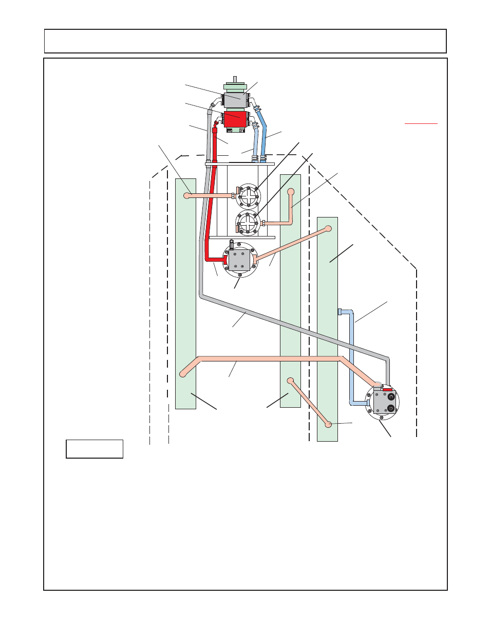
10 FT - PUMP & MOTOR HYDRAULIC SCHEMATIC
12345678901234567
12345678901234567
12345678901234567
12345678901234567
12345678901234567
12345678901234567
12345678901234567
12345678901234567
12345678901234567
12345678901234567
12345678901234567
12345678901234567
12345678901234567
12345678901234567
12345678901234567
12345678901234567
12345678901234567
12345678901234567
12345678901234567
12345678901234567
12345678901234567
12345678901234567
12345678901234567
12345678901234567
12345678901234567890123456
12345678901234567890123456
12345678901234567890123456
12345678901234567890123456
12
12
12
12
12
12
12
12
12
12
12
12
12
12
12
12
123
123
12
12
123
123
123
123
123
123
1
2
3
4
5
6
7
8
9
10
11
12
13
14
15
16
17
CAUTION !
NEVER
Connect Pump Pressure Line
direct to cooling tubes, as it
will damage the tubes.
Center (LH & RH)
Cooling Tubes
R-Wing
Cooling
Tube
Figure 3
Wing Supply (Front) Pump Half
Center Supply (Rear) Pump Half