Pump service & repair – Alamo HYDRO 15 User Manual
Page 37
Section 2 - 21
HYDRO 15 (Service Manual) 09/06
© 2006
Alamo Industrial
PUMP SERVICE & REPAIR
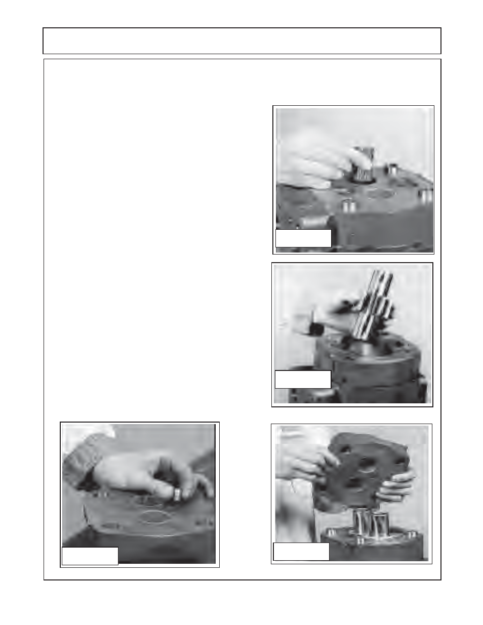
Figure 43
Figure 44
Figure 46
Figure 45
22.
Gently slip the thrust plate
(figure 10 item 7 & 8)
into the
gear housing and into place on the shaft end
(figure 46).
The
channel seal from
should face the port end cover. The relief
groove in the thrust plate should face the outlet side of the
pump
(see figure 23A & 24).
The correct installation of the
thrust plate and channel seal are very important, DO NOT
install them wrong.
23.
Make certain the bushings are OK or have been replaced
correctly
(see step 5, 6 & 7)
. Place the port end cover over the
gear housing making certain your alignment marks
(figure
23A)
are aligned and the gear journals of the gear set have
a light coat of grease on them Recheck the gasket seal
(figure 10 item 10)
is still
in place. Tap the port end cover
lightly in the center, make certain that the dowel pins are
aligned, cover should fit flush on gear housing
(figure 46).
24.
Thread the bolts & lockwashers in through shaft end
cover and gear housing until threads are started into bearing
housing. Alternately tighten the bolts in increments that will
make the three components pull down evenly
(figure 47).
Torque the bolts in
increments until the bolts
(qty 4)
are
torqued to
200 ft. lbs.
25
Review all assembly steps to make certain the assembly
is correct. Wipe and clean any grease that may be on the
outside of pump. Reconnect hoses to pump
(figure 9).
21.
Check the plug in the port end housing
(figure 10 item 5)
. These plugs do not have to be removed unless the
port end housing
(figure 10 item 17)
is being replaced or someone has removed the plug. The plug must be
installed on the correct side to function properly. If plugs need to be installed, removed or re-installed refer to
steps 3 & 4
in the assembly instructions on correct way to install plugs
(figure 27, 28 & 45).