Standard axle lift cylinder repair – Alamo HYDRO 15 User Manual
Page 93
Section 5 - 19
HYDRO 15 (Service Manual) 10/06
© 2006
Alamo Industrial
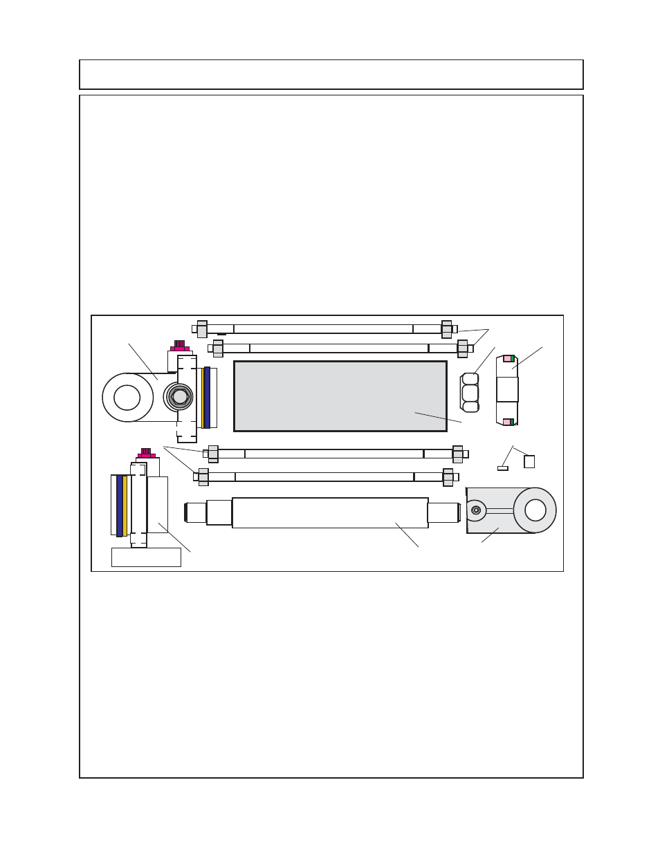
STANDARD AXLE LIFT CYLINDER REPAIR
Clean & Inspect Cylinder Components: ( Axle Lift Cylinder, Standard)
1.
Clean and inspect parts
(figure 6)
, check cylinder components, look for wear, operation damages,
condition of materials. Make certain the piston, cylinder rod, barrel, base clevis, cyl head, rod clevis,
tie-rods and nuts, clevis set screw, cylinder rod. Remove the old seals and seal components
(figure
4, 5 & 6).
Inspect the tie-rods and the tie-rod hex nuts. The tie-rods may need the threads cleaned
and/or straightened.
2.
All components cleaned and inspected, replace any damaged parts.The Piston Locknut
(figure
6 item 14)
is recommended that it be replaced with new locknut of same rating. Make a note of which
way the seals are installed and in what order. Remove all old seals and replace them with new ones
(see figure 6),
The nylon thread protector will need to be removed from the rod clevis and replaced
(figure 6 item 2).
3.
After the seals have been removed inspect all of the grooves where seal seat for condition, make
certain none are bent or distorted, they should not have any damage or wear severe enough to
damage seals. Check for wear, the ID of the barrel
(figure 6 item 5)
, OD of the piston
(figure
6 item
15)
, ID of the cylinder head
(figure 6 item 9)
.
Cylinder Re-Assembly: (Axle Lift Cylinder, Standard)
1.
Clamp cylinder rod clevis into bench vise
(figure 6 item 3 see figure 7)
. Make certain the old
nylon seal protector has been removed before attempting to screw cylinder rod into clevis.
(figure
6 item 2). Using
a strap wrench if needed screw the cylinder rod
(figure 6 item 4)
into the clevis
(figure 6 item 3)
, tighten rod until it is screwed in flush with cylinder rod
(see figure 7)
. Important!
DO NOT
install nylon thread protector or setscrew
(figure 6 item 2)
into clevis at this time, it is best
to do this later after piston and piston nut has been installed.
2.
Replace the seals in the cylinder head
(figure 6 item 9),
base clevis
(figure 6 item 8)
and piston
(figure 6 item 15)
. Make certain to put the seal on in the correct order
(figure 6 & 7).
3
Installing the Piston on the cylinder rod (figure 6 & 7 item 15) may require a press,
DO NOT
try to press piston onto cylinder rod with the piston nut.
Use Locktite 271 or equivalent
when
pressing piston onto cylinder rod. Make certain piston and rod are in alignment when pressing
piston, make certain piston and rod are protected from damage.
Figure 6
6 & 7
3
4
5
9
8
15
14
12345678
12345678
12345678
12345678
12345678
12345678
12
12
12
12
12
123456
123456
123456
123456
123456
123456
123456
123456
123456
123456
123456
123456
123456
123456
123456
123456
123456
123456
123456
123456
123
123
123
12
12
12
12
12
12345
12345
12345
12345
12345
12345678
12345678
12345678
12345678
12345678
12345678
12345678
12345678
12345678
12345678
12345678
12
12
12
123
123
123
1234567
1234567
1234567
1234567
1234567
1234567
12
12
12
12
1234567
1234567
1234567
12345678
12345678
12345678
12
12
12
12
12
12
1234
1234
1234
1234
2
6 & 7